Intended Audience
This paper is intended for OpenVMS system administrators who are planning to
install and run OpenVMS on the BL8x0c i2 hardware. It provides quick reference
information, as well as details on how to install and configure various hardware
components, troubleshoot, and configure the Integrity i2 server blades.
Abbreviations
|
CLI |
Command Line Interface |
|
CM
|
Command Menu |
|
DIMM |
Dual-in Line Memory Module |
|
FC
|
Fiber Channel |
|
GUI |
Graphical User Interface |
|
iLO |
Integrated Lights Out |
|
ICH |
I/O Controller Hub |
|
LOM |
LAN On Motherboard |
|
LUN |
Logical Unit Number |
|
OA |
Onboard Administrator |
|
ORCA |
Option ROM Configuration for Arrays |
|
SAS |
Serial
Attached SCSI |
|
SCSI |
Small Computer System Interface |
|
SUV |
Serial, USB and VGA |
|
USB |
Universal Serial Bus |
|
VC |
Virtual Connect |
VCM |
Virtual
Connect Manager |
Introduction to HP Integrity BL8x0c i2 Server Blade
We know that blades have advantages with respect to more processing power in
less space, simplified cabling, storage, maintenance and shared resources. A
single enclosure can house multiple servers that share power source and other
components, and also consolidate related resources, such as storage and
networking equipment, into a smaller architecture than would be the case with a
farm of regular servers.
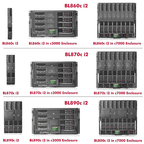
BL8x0c i2 is a full-height Integrity server blade with the Intel Itanium 9300
processor series. The family of BL8x0c i2 products includes single blade 2S
(BL860c i2), dual blade 4S (BL870c i2), and quad blade 8S (BL890c i2) variants
(where S represents the number of CPU sockets), each capable of running a single
operating system image across all blades/sockets. The Intel Itanium 9300
processor is available both as quad-core and also as dual-core.
BLADE |
SOCKETS
(Cores) |
DIMM Slots |
Max. Memory
Support (with 8GB DIMM's) |
No of PCIe
Mezz Cards |
No of SAS
Hard Disks |
BL860c i2 |
2S (8 Cores) |
24 |
192 GB |
3 |
2 |
BL870c i2 |
4S (16 Cores) |
48 |
384 GB |
6 |
4 |
BL890c i2 |
8S (32
Cores) |
96 |
768 GB |
12 |
8 |
BL860c i2 Blade Components
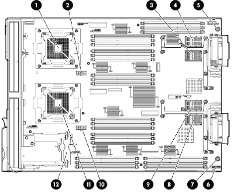
| 1 |
CPU 0 |
| 2 |
CPU 0
POWER CONNECTOR |
| 3 |
TYPE
1 MEZZANINE CONNECTOR SLOT 1 |
| 4 |
TYPE
1 or 2 MEZZANINE CONNECTOR SLOT 2 |
| 5 |
THUMBSCREW 1 |
| 6 |
BATTERY |
| 7 |
THUMBSCREW 2 |
| 8 |
ICH
MEZZANINE CONNECTOR SLOT |
| 9 |
TYPE
1 or 2 MEZZANINE CONNECTOR SLOT 3 |
| 10 |
CPU 1
POWER CONNECTOR |
| 11 |
CPU 1 |
| 12 |
SAS
BACK PLANE |
For complete preparation and installation guidelines for the BL8x0c i2 server
in the c-class enclosure, see the HP Integrity BL860c i2, BL870c i2,
and BL890c i2 Server Blade User Service Guide:
http://bizsupport2.austin.hp.com/bc/docs/support/SupportManual/c02110937/c02110937.pdf
c-CLASS Enclosures
HP offers two versatile c-Class enclosure models:
- HP Blade System c7000 Enclosure
- HP Blade System c3000 Enclosure
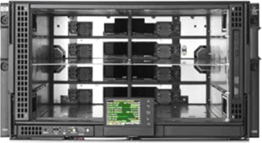
The c7000 provides 16 device bays and eight interconnect module bays in a 10U
rack-mount configuration.
C7000 Enclosure Front View
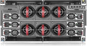
C7000 Enclosure Rear View
C3000 Enclosure Front View
The c3000 provides eight device bays and four interconnect module bays in a
6U rack-mount or tower configuration.
C3000 Enclosure Rear View
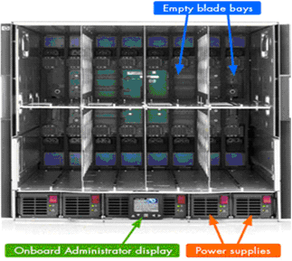
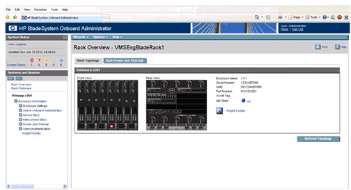
Both enclosure models also include the Onboard Administrator and the Insight
Display diagnostic panel. They use the same hardware, software, and processes
for management.
Onboard Administrator
The core of c-class enclosure management is the Blade System Onboard
Administrator module. It performs four management functions for the entire
enclosure:
- Detect component insertion and removal
- Identify components and required connectivity
- Manage power and cooling
- Control components
The following methods are different ways for technicians and administrators
to access the Onboard Administrator:
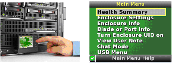
An Insight Display screen on each HP Blade System c-class enclosure provides
ready access for quick setup and daily maintenance.
Onboard Administrator Command Line Interface (CLI)
The Onboard Administrator CLI allows administrators to use serial, telnet, or
SSH connections to control enclosure and device operation, including the use of
scripts for automation. CLI commands include commands to connect to the iLO on
each compute blade and to any supported interconnect module management
processors such as Virtual Connect.
Onboard Administrator Graphical User Interface
The GUI provides remote administration capabilities from a desktop web
browser. The GUI allows administrators to simplify tasks such as managing users
and network settings, virtual power control, boot order control, and enclosure
DVD attachment to one or more blades. The GUI can also simplify administrative
tasks when identical operations are performed on multiple compute blades.
The GUI contains graphical views for server-to-interconnect port mapping, zone
cooling measurements, and power use history. At a glance, the administrator can
tell if any devices in the enclosure need attention. If multiple enclosures in a
rack are connected using the enclosure links, the administrator can view and
control one or more enclosures from a single GUI.
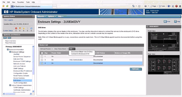
Enclosure DVD
The Onboard Administrator (OA) can provide USB CD/DVD drive connectivity to
one or more servers in an enclosure with the enclosure DVD feature. In addition,
with a USB key plugged into the Onboard Administrator, ISO files can be
connected to one or more servers, the OA firmware can be updated from a file,
and the enclosure configuration can be saved or restored from a file on the USB
key. This feature can dramatically simplify the firmware update of all servers,
the Onboard Administrator modules, or initial setup of an enclosure from a
custom configuration file.
DVD window
access from OA Web Interface
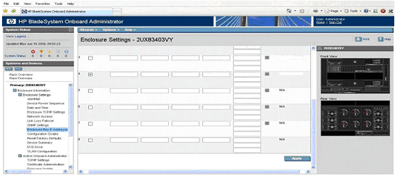
Enclosure Bay IP Addressing
The Onboard Administrator significantly enhances the
management network infrastructure by offering a single point to assign IP
addresses to the compute blade iLO management ports and the interconnect module
management ports.
Integrated Lights-Out (iLO) Web Interface
HP Integrity Integrated Lights-Out (iLO) simplifies remote
management of your Integrity servers from anywhere in the world.
Shown below is the iLO web
interface:
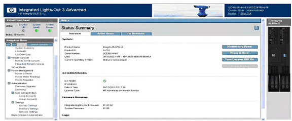
iLO can be used to connect to system serial
console using “remote serial console” option and also install the operating
system using vMedia option. iLO also supports Integrated Remote Console which
provides a high-performance graphical remote console.
Prerequisites
To setup or to configure the HP Integrity BL8x0c i2 server blades, the
following prerequisites for hardware, firmware and software must be met:
- C7000 and/or C3000 c-class enclosures.
- Onboard Administrator firmware – recommended version.
- BL8x0c i2 Blade and required/necessary IO cards have to be updated with
the latest supported firmware version.
- SUV Cable for Serial, USB and VGA connectivity.
- Respective IP’s (OA, MP LAN) have to be configured.
- OpenVMS V8.4 for Integrity server kit in ISO or BCK format.
- HP DVD burnt with OpenVMS V8.4 ISO.
- Update kits for OpenVMS V8.4 for Integrity servers.
Overview of BL8x0c i2 server blades setup
To setup the BL8x0c i2 server blades, follow these steps regarding logging
into OA and upgrading OA firmware:
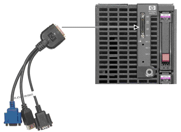
- Plug the BL8x0c i2 blade to the C7000 or C3000 enclosure.
- Connect the SUV cable to the SUV port on the Server Blade. Access the blade
using the serial port (RS232 port) on the SUV cable, which is the cable with 3
ports or serial, USB and VGA.
- Assign the Onboard Administrator (OA) IP address on the OA console present
on c-Class enclosure.
- Enter the username and password from the tag supplied with the OA module to
access the remote OA web interface and complete the OA first-time installation
wizard.
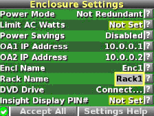
- The enclosure information screen displays information about the enclosure, including the following
details:
- Active OA IP address
- Active OA service IP address
- Current health status of the enclosure
- Current enclosure ambient temperature
- Current AC input power to the enclosure
- Enclosure name
- Rack name
For detailed procedure, see the HP BladeSystem c7000/c3000 Enclosure
Setup and Installation Guide:
C7000:
http://h20000.www2.hp.com/bc/docs/support/SupportManual/c00698286/c00698286.pdf
C3000: http://h20000.www2.hp.com/bc/docs/support/SupportManual/c01167165/c01167165.pdf
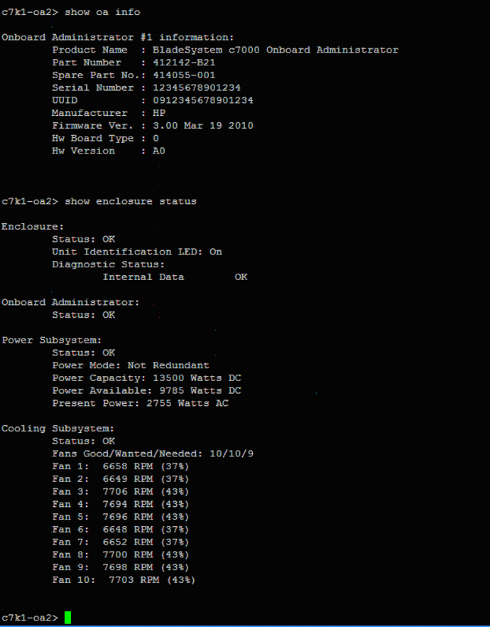
- OA firmware version can be obtained either from the web interface of the OA
or from the OA’s Command Line Interface (TELNET session) using the SHOW OA INFO
command.
- Based on the information displayed, it can be upgraded to the recommended
firmware version. For more information about OA firmware and installation
instructions, see the following website:
http://h20000.www2.hp.com/bizsupport/TechSupport/SoftwareIndex.jsp?lang=en&cc=us&prodNameId=4204753&prodTypeId=3709945&prodSeriesId
=4186428&swLang=13&taskId=135&swEnvOID=4094
Logging into MP and configuring MP LAN:
- Login to the blade MP using the username and password present on the blade
server tag. Type CM to reach the MP command menu and create a new user with the
necessary access setting.
- From the MP command menu issue the command LC (LAN Configuration) to
configure the MP LAN. If you do not have a DHCP server on your local network,
and are assigning a static IP address to the server blade, you must disable DHCP
on the server blade. To add static IP address, subnet masks, and gateway
address, follow these steps:
NOTE: Obtain the required addresses from a system administrator.
- From the MP Main Menu, enter the “CM” command, which brings up the MP
command menu screen is displayed.
- Enter the “LC” command, LC Menu screen is displayed. At each prompt you may
type DEFAULT to set the default configuration or Q to Quit.
Default LAN Configuration: - -MAC Address :0x00110aa50058
D - DHCP Status : Disabled
I - IP Address : 0.0.0.0
M - MP Host Name : ilob5122
S - Subnet Mask : 0.0.0.0
G - Gateway Address : 0.0.0.0
L - Link State : Auto Negotiate
O - Duplex Option : n/a
R - Remote Serial Console Port : 2023
H - SSH Access Port : 22
Enter parameter(s) to change. A to modify All. Or (Q) to Quit:
- From the LC
Menu, you can select any of the options as follows:
- Enter “d” to access the DHCP status screen and follow the onscreen
instructions to change the DHCP status from Enabled to Disabled.
- Enter “Y” to confirm the DHCP status change.
- Enter “I” to access the IP Address screen and follow the onscreen
instructions to add static IP address obtained from the system
administrator.
- Enter “S” to access the subnet mask screen and follow the onscreen
instructions to add subnet mask address obtained from the system
administrator.
- Enter “G” to access the gateway address screen and follow the onscreen
instructions to add gateway address obtained from system administrator.
- Verify the configuration and confirm the changes.
- The server blade is now set up for remote access with static IP address.
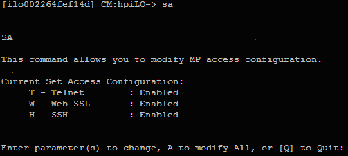
- Enable
TELNET access using the “SA” command.
- Reset the MP using the XD -R –NC command. You can access MP/iLO by using the
web interface and also by using the TELNET session on the Remote console.
Upgrading MP firmware:
- From the MP Command Menu (CM), check the blade firmware version using the
command “SR” or “SYSREV” command. Upgrade the firmware to the recommended
version and also ensure that the firmware for the respective IO Cards (LOM, SAS
and so on) are the latest versions.
- For the steps to obtain and update the firmware, see:
http://h20000.www2.hp.com/bizsupport/TechSupport/SoftwareIndex.jsp?lang=en&cc=us&prodNameId=4204753&prodTypeId=3709945&prod
SeriesId=4186428&swLang=13&taskId=135&swEnvOID=54
Getting to EFI and
configuring LUN:
- POWER ON the system and get to the SHELL prompt.
- MAP -R command on the Shell> provides the list of disks (BLKx device).
If no disks are detected, the LUNs are not created.
- To create LUNs use the DRVCFG command provided by ORCA utility. For a
detailed procedure on how to use DRVCFG command, see section “BL8x0c i2
Troubleshooting Methods."
- After the LUN’s are created, and the controller is restarted, the shell
“MAP -R” command must display the BLKx devices.
- Install OpenVMS using one of the following methods as described in
section “Methods to Install OpenVMS."
Methods to Install OpenVMS
OpenVMS can be installed on an Integrity server system
using any one of the method as explained below.
vMedia
For a detailed description on
how to install OpenVMS using vMedia, see the HP OpenVMS Version 8.4 Upgrade
and Installation Manual at:
http://h71000.www7.hp.com/doc/84final/ba322_90087/ba322_90087.pdf.
External or Internal USB DVD Drive
Note: C3000 enclosure has an internal USB DVD Drive
which can be connected to a particular blade using the Onboard
Administrator.
The C7000 enclosure does not have an internal DVD drive, but an external USB
DVD drive can be connected to a USB port via a SUV cable. This method can be
used on C3000 enclosure as well.
Insert the OpenVMS V8.4 DVD into the respective DVD drive and boot the
system with the DVD, which provides the options to install or upgrade
OpenVMS.
InfoServer
For a detailed description on
how to setup the InfoServer and install OpenVMS using InfoServer, see the
HP OpenVMS Version 8.4 Upgrade and Installation Manual at:
http://h71000.www7.hp.com/doc/84final/ba322_90087/ba322_90087.pdf
The following examples below explain how to perform the
InfoServer boot.
Example 1: InfoServer boot with memory disk and directed lanboot and
without DBPROFILE:
SHELL> LANBOOT SELECT -SIP <SERVER IP> -CIP <CLIENT IP>
-GIP <GATEWAY IP> -M <SUBNET_MASK> -B
"<FULL PATH TO THE BOOT FILE ON THE BOOT SERVER>
"-OD "-FL 0,200400 -SERVICE <SERVICE NAME>"
Example 2: InfoServer boot without memory
disk and with directed lanboot (by choosing services)
SHELL> LANBOOT SELECT -SIP <SERVER IP> -CIP <CLIENT IP>
-GIP <GATEWAY IP> -M <SUBNET MASK> -B
"<FULL PATH TO THE BOOT FILE ON THE BOOT SERVER>"
VMS Kit Disk on SAS Disk
Copy the OpenVMS saveset on to BL8x0c i2 server blade
running OpenVMS and perform the following steps. For example, let us assume
DKA0: as a target device (VMS kit disk).
NOTE: This method can be used on a system that already has OpenVMS installed and
running.
- Foreign mount the target disk on which the kit disk has to be created
using the following command:
$ MOUNT /FOREIGN DKA0:
- Take a back up of the OpenVMS V8.4 saveset onto the target disk using the
following command:
$ BACKUP /IMAGE I64V84.BCK /SAVE DKA0:
- After the backup is complete, dismount the target disk using:
$ DISMOUNT DKA0
Now the target disk is ready to be used as a kit disk. Boot the system with
the newly created kit disk, which provides the options to install or upgrade
OpenVMS.
VMS Kit Disk on a USB Flash Drive/Disk
Note: USB flash drives/disks are not supported on OpenVMS.
However, some makes of flash drives are found to work with OpenVMS. The minimum
size of the USB flash drive/disk required for this procedure must be 5 GB. HP
recommends using this method if none of the above options are feasible.
To create a VMS kit disk on a USB flash drive/disk, you can use one of the
following methods:
Method 1
Copy the OpenVMS V8.4 saveset onto system running OpenVMS and perform the
following steps. Plug the USB flash drive/disk to the USB port. This device will
be configured as DNxx device.
NOTE: This is only possible on a system that already has OpenVMS installed and
running. If this method needs to be used on a fresh system, then the kit disk
needs to be created on another system running OpenVMS.
For example, let us assume DNA0: as a target device (VMS kit disk).
- Mount the USB flash drive/disk (DNA0:) which can be made bootable (kit
disk) as foreign, using the following command:
$ MOUNT /FOREIGN DNA0:
- Take the back up onto the target disk by using the following command:
$ BACKUP /IMAGE I64V84.BCK /SAVE DNA0:
- After the backup is complete, dismount the target disk using:
$ DISMOUNT DNA0
Now USB kit disk is ready. Plug the USB flash drive/disk (kit disk) to the
USB port on the SUV of the target BL8x0c i2 system. Boot the system using the
USB flash drive/disk (kit disk), which provides the options to install or
upgrade OpenVMS.
Method 2
Place the OpenVMS V8.4 ISO on
the Windows desktop and then plug in the USB flash drive/disk and perform the
following steps:
- Login to the
iLO web interface and launch vMedia.
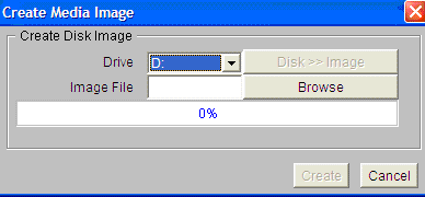
- Click Create Disk Image on the vMedia window.
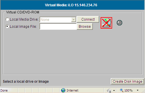 The
Create Media Image window appears:
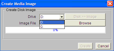
- Click
Drive menu and select the USB Drive as shown below, where, G: is the
USB flash drive/disk.
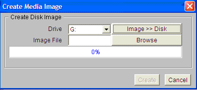
- To create
VMS kit disk on a USB flash drive/disk from an OpenVMS V8.4 ISO image file,
click the Disk>>Image to change it to Image>>Disk.
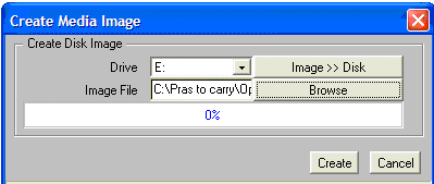
- Click Browse and specify the location of the OpenVMS V8.4 ISO image file.
- Click Create to start the preparation of VMS kit disk on a USB flash
drive/disk.
- Plug the USB
(kit disk) to the BL8x0c i2 and boot the system, which provides options to
install or upgrade OpenVMS.
NOTE: Booting the system either with VMS kit disk or DVD or
vMedia or InfoServer -- as explained above -- provides the following options to
install or upgrade the OpenVMS.
You can install or upgrade the OpenVMS Integrity server’s operating system or
you can install or upgrade layered products that are included on the OpenVMS
Integrity server’s distribution media (CD/DVD).
You can also execute DCL commands and procedures to perform "stand-alone" tasks,
such as backing up the system disk.
Choose one of the following:
- Upgrade, install, or reconfigure OpenVMS Integrity servers Version 8.4
- Display layered products that this procedure can install
- Install or upgrade layered products
- Show installed products
- Reconfigure installed products
- Remove installed products
- Find, install, or undo patches, as well as show or delete recovery data
- Execute DCL commands and procedures
- Shut down this system
For detailed installation
or upgrade procedure information, see the HP OpenVMS Version 8.4 Upgrade
and Installation Manual at:
http://h71000.www7.hp.com/doc/84final/ba322_90087/ba322_90087.pdf
Virtual Connect Technology
Introduction to Virtual Connect
Virtual Connect is the next step in virtualization that
extends the benefits of virtualization beyond the server to other
infrastructure.
Virtual Connect accomplishes this by defining a server connection profile
for each server in the enclosure before the server is installed. These
defined profiles establish MAC addresses for all the network adapters, world
wide numbers for all the host bus adapters and SAN boot parameters.
Previously, network administrators only had two options to connect each of
the servers to the outside world, either through pass-through or switches.
With HP Virtual Connect Architecture, they will be able to manage the entire
blade architecture, thereby reducing the burden of managing hundreds of
switches and cables and thus reducing the cost.
HP Virtual Connect Enterprise Manager
HP Virtual Connect
Enterprise Manager (VCEM) is a management option for multiple BladeSystem
enclosures configured with Virtual Connect. VCEM provides a central console
that aggregates Virtual Connect resources, improves productivity, and
enables faster response to changing data center workload demands. It also
provides a single console to manage upto 800 BladeSystem enclosures and runs
on Virtual Connect Enet Module.
HP Virtual Connect Flex-10 Technology
Virtual Connect Flex-10
technology builds even more flexibility into each server blade to add up to
4 times as many NIC connections, fine tuning the bandwidth for each
connection. It helps remove up to 75 percent of server edge infrastructure,
lower purchase costs by up to 66 percent, and reduce power consumption up to
50 percent. It also enables you to transform your infrastructure and uncover
its full potential.
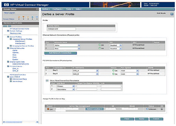
Virtual Connect Manager
The VC Manager contains
utilities and profile wizards that allows the system administrators to
create and allocate server connection profiles to servers. The server
profiles include the Ethernet MAC addresses and Fiber Channel HBA world wide
names or WWNs and SAN boot configurations.
Here is the sample screen shot
of the VCM:
Virtual Connect Firmware
For more information about
Virtual Connect firmware and upgrade procedures, see the following website:
http://h20000.www2.hp.com/bizsupport/TechSupport/SoftwareIndex.jsp?lang=en&cc=us&prodNameId=4204762&prodTypeId=3709945&prod
SeriesId=4186432&swLang=13&taskId=135&swEnvOID=4001#29154
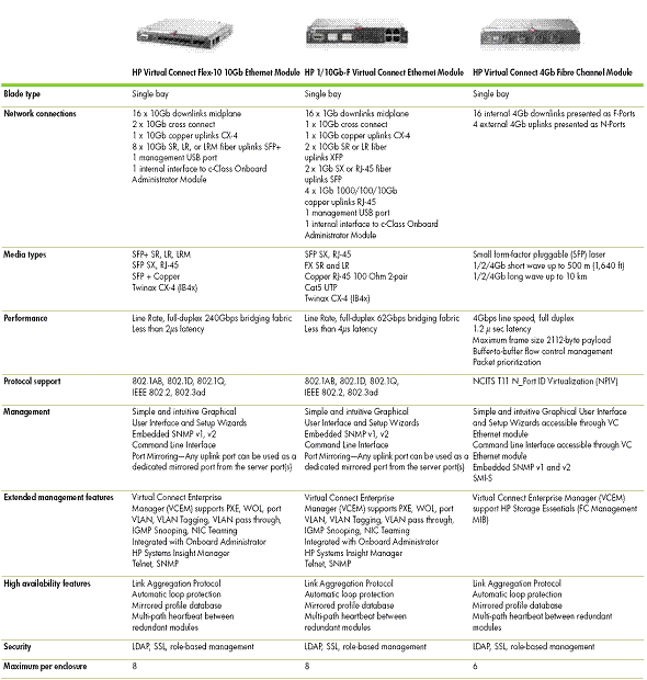
Virtual Connect Ethernet Modules
This section provides a list
of various VC Ethernet modules and their specifications.
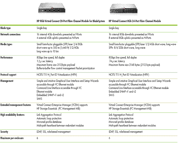
Virtual Connect Fiber Channel Modules
This section provides a list of various VC Fiber Channel
modules and their specifications.
BL8x0c i2 Troubleshooting Tips
This section provides the
BL8x0c i2 troubleshooting tips.
- Connecting power cables to C7000 enclosure
The order in which the
power cables are connected to the C7000 enclosure is important. If the order
is not followed properly, it results in powering up only a few power
modules.
There are 6 power ports and the power cables must be connected in the
following order:
Power SLOT 1 and Power SLOT 4
Power SLOT 2 and Power SLOT 5
Power SLOT 3 and Power SLOT 6
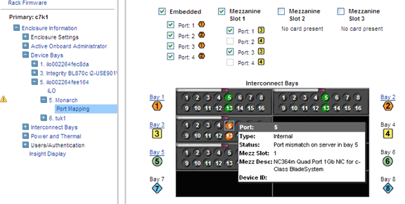
- Port mapping of server blade to interconnect module
Ensure correct
port mapping for proper operation of blades. If there is any mismatch in
port mapping, it results in server blade degradation.
Port mapping of each server blade to interconnect module in the back plane
can be viewed from the Onboard Administrator (OA) web interface. The figure
below captured from the OA depicts the port mapping of the mezzanine cards
in the server blade to the interconnect module in the interconnect bay with
appropriate status.
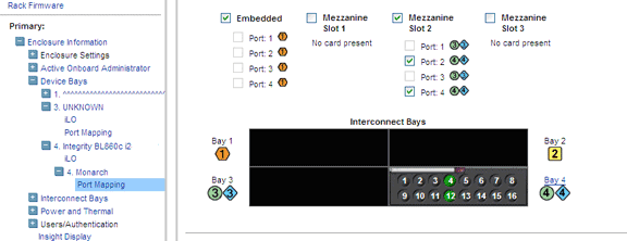
If there is any mismatch in the port mapping, it will be highlighted in the OA
web interface as shown below:
Proper port mappings on C7000 enclosure is as shown:
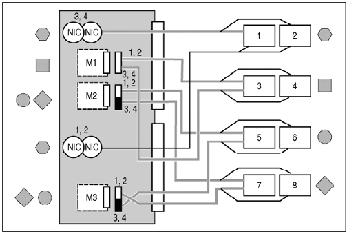
For
detailed procedure, see the HP BladeSystem c7000 Enclosure Setup and
Installation Guide at:
http://h20000.www2.hp.com/bc/docs/support/SupportManual/c00698286/c00698286.pdf.
Proper port mappings
on C3000 enclosure is as shown:
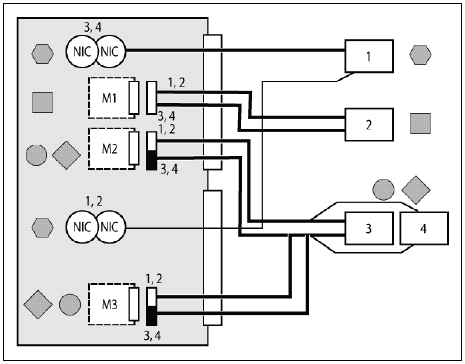
For detailed procedure, see the HP BladeSystem c3000 Enclosure Setup and
Installation Guide at:
http://h20000.www2.hp.com/bc/docs/support/SupportManual/c01167165/c01167165.pdf
- 4S (BL870c i2) and 8S (BL890c i2) setup
If you
want to configure your blades as required to scale up/down needs, the
following tip is useful:
4-Socket configuration (BL870c i2): Connect the two 2S blades (BL860c
i2) using scalable blade link. The left most blade will always be the
monarch and the other blade will be the auxiliary. Reset the monarch from
the Onboard Administrator, and this will setup the 4S configuration.
8-Socket configuration (BL890c i2): Connect the four 2S blades
(BL860c i2) using scalable blade link. The left most blade will always be
the monarch and the other blades will be the auxiliaries. Reset the monarch
from the Onboard Administrator, and this will setup the 8S configuration.
NOTE: Upgrading the firmware on the monarch will automatically upgrade the
firmware on the auxiliary as well.
- Creating LUNs using ORCA utility
If LUNs are not created, then the respective SAS disk devices cannot be
detected.
a. Create LUNs using the DRVCFG command from
EFI (SHELL>)
b. Find the “SAS driver ID” using the following command: SHELL> drivers
‘
‘
‘
A4 00000318 B X X 1 2 Smart Array SAS Driver v3.18
MemoryMapped(0xB,0x
‘
‘
Where:
‘A4’ is the SAS driver ID.
c. Obtain the respective “controller ID” using the following command:
SHELL> DRVCFG
This command lists a series of SAS driver IDs and their respective
controller IDs as shown in the figure:
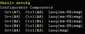
In this example, ‘A4’ is the “SAS Driver ID" and its “controller
ID" is
‘A3.‘
d. Launch the ORCA utility using the respective driver ID and controller
ID obtained from above steps:
SHELL> DRVCFG A4 A3 -s
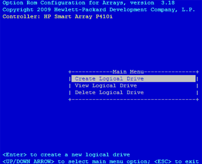
e. Select Create Logical Drive option and then create the LUNs.
f. Click Yes to restart the controller.
From the SHELL> execute the MAP –R command to list the devices.
- AUTOGEN unable to create page, swap, and dump files of appropriate sizes
On systems with large physical memory, sometimes AUTOGEN does not create
page, swap and dump files of appropriate size. HP recommends that the system
manager review the AUTOGEN feedback report named
SYS$SYSTEM:AGEN$PARAMS.REPORT and create the page, swap, and dump files of
required sizes manually once the system boots up. See the
AGEN$FEEDBACK.REPORT for any AUTOGEN error messages and take appropriate
actions.
- Ensure to assign MP IP to monarch and its auxiliaries in 4S/8S
configuration
The firmware upgrade fails if the MP IP is assigned only to monarch but
not to auxiliaries. To ensure proper firmware upgrade, it is necessary to
assign the MP IP’s to the auxiliaries as well.
References
|