|
Search this site
powered by FreeFind |
|
|
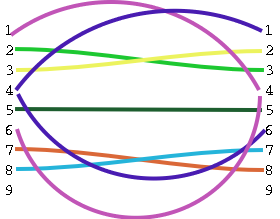
| Signal Name | DB-25 Pin | DB-9 Pin | DB-9 Pin | DB-25 Pin | ||
| FG (Frame Ground) | 1 | - | X | - | 1 | FG |
| TD (Transmit Data) | 2 | 3 | - | 2 | 3 | RD |
| RD (Receive Data) | 3 | 2 | - | 3 | 2 | TD |
| RTS (Request To Send) | 4 | 7 | - | 8 | 5 | CTS |
| CTS (Clear To Send) | 5 | 8 | - | 7 | 4 | RTS |
| SG (Signal Ground) | 7 | 5 | - | 5 | 7 | SG |
| DSR (Data Set Ready) | 6 | 6 | - | 4 | 20 | DTR |
| CD (Carrier Detect) | 8 | 1 | - | 4 | 20 | DTR |
| DTR (Data Terminal Ready) | 20 | 4 | - | 1 | 8 | CD |
| DTR (Data Terminal Ready) | 20 | 4 | - | 6 | 6 | DSR |
|
Search this site
powered by FreeFind |
|
|