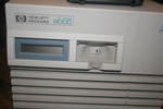
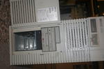
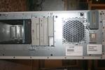
Visible is the HP 9000 logo, the system status screen and the power switch behind a protective flap.
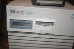
This photo shows the flap open. Doesn't look much different.
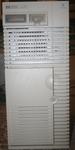
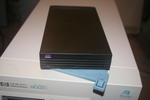
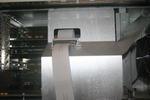
Front of the system with the door closed.
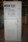
Mostly the same as the front-1 image.
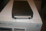
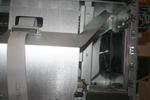
Sideways picture of the front with the door open. Visible is the CD-ROM drive, DDS3 tape drive and hot-swap cadge with one drive installed.
Front of the disk caddy. The blue bit is a lever to make removing it easier.
Rear of the disk caddy.
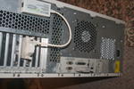
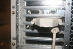
Rear o the system showing 3 installed cards, fans and the rear ports.
SCSI terminator for the Fast-Wide SCSI Card.
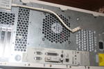
A picture of the rear ports. The cable hanging down plugs into the remote management board. The device plugged in to one of the ports is a SCSI Terminator.
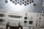
A closeup of the rear ports.
The modem for the remote management board.
The front of the system with the plastic cover removed.
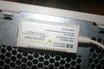
The sticker on the inside of the cover. On the right you can see a fairly large dent. It seems as if at some point the system unit was dropped from a small height onto some stairs or something, leaving a large dent in the bottom edge. Due to the way the c
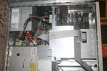
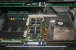
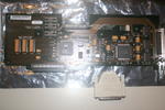
Inside the system.
Inside the system again, focusing on the front area.
Visible is an air baffle covering part of the CPU board and the cards. The SCSI cable goes through a hole in the top.
A fan is present in the front of the case.
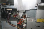
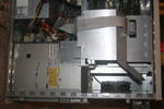
The lower section of the system. The PSU can be seen in the bottom left, above it a large fan, on the right is the drive cadge.
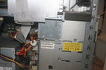
Image focusing on the drive cadge.
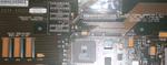
The CPU board.
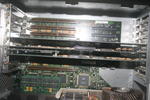
3 cards installed in the system. They all seem to be using the "Turbo HSC" plugs - nothing is attached to the brown ones.
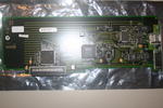
An Ethernet controller using the DEC 21140 chip. It connects to the "Turbo HSC" plugs on the motherboard.
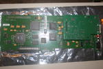
The remote management board. Comes in two PCBs. The small black connector to the right on the bottom edge of the board plugs into a set of pins on the motherboard, along with the large "Turbo HSC" plug next to it.
A SCSI board and its terminator. It has a strange setup for its internal bus termination.
Internal bus termination for the SCSI Board. When the internal bus is not used, the yellow terminators are moved into the sockets at the top of the board.
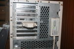
Photo of the cards on the rear of the system. The box on the right is for the remote management board and is not currently plugged in.