| Previous | Contents | Index |
The following section describe unsolicited data collection and pollset
for the DAS for AB INTERCHANGE software.
3.4.1 Unsolicited Data Collection
BASEstar Classic device connection management can receive data values generated by plant devices without issuing a request. To use this unsolicited data collection capability, the devices and physical points must be correctly defined using BASEstar Classic software. For information on defining devices and data for unsolicited collection, refer to the BASEstar Classic Command Line Interface User's Guide.
Allen-Bradley devices can send unsolicited messages to the VAX host. To enable unsolicited messaging, define the device (and any required physical points) as unsolicited and enable the device, as follows:
DCM> MODIFY DEVICE device_name /UNSOLICITED/ENABLE |
Messages sent from the PLC's and received by the DAS through the INTERCHANGE software are identified by an identifier. This identifier is referred to in INTERCHANGE documentation as the application address. In BASEstar Classic software, this is the unsolicited identifier, whose format is an octal value ranging from 0 to 77777.
Unsolicited data may be sent from multiple devices with the same ID, only if the size and format are consistent. The INTERCHANGE software will reject unsolicited messages that are inconsistent. The maximum unsolicited message size is 2000 bytes for local PLC-5/250 or 236 bytes for devices connected to a Pyramid Integrator via Data Highway.
The DAS for AB INTERCHANGE software supports only unique unsolicited identifiers defined for an individual device.
Compaq recommends that the address of the phypoint match the PLC-5 Data Table Address of the message instruction.
The Allen-Bradley PLC-5/250 and PLC-5 family sends unsolicited data to the VAX and through the INTERCHANGE software by means of the message (MSG) instruction. The values of some elements in the message instruction are critical for successfully sending data from the PLC to the DAS. The critical definitions in the message instruction are listed in Table 3_14 and Table 3-15.
| Command field | Value |
|---|---|
| Communication Command: | PLC-2 UNPROTECTED WRITE |
| Size in elements: | Must match the format of the unsolicited point |
| Destination Data Table Address | The unsolicited ID value |
| Local/Remote | Local |
| Local Node Address | DH/DH+ address of the EI module |
| Command field | Value |
|---|---|
| Module ID | CLASS= UAM |
| Local/Remote | Local |
| Local Node Address | DH/DH+ address of the EI module |
| Communication Command: | PLC-2 UNPROTECTED WRITE |
| External Data Addr | The unsolicited ID value |
| Requested Size: | Must match the format of the unsolicited point |
For more specific information on how to program the PLC's, refer to the Allen-Bradley INTERCHANGE reference and the programming manuals for the PLC-5/250 and PLC-5.
The following is an example of an unsolicited phypoint definition. This phypoint is a 100 word array starting at address $N17:0 on device DTL5. The unsolicited ID is 200 octal.
DCM> DEFINE PHYPOINT -
                        /DEV=DTL5 -
                        /ADDR="$N17:0" -
                        /FORM=ARRAY[100]:WORD -
                        /UNSOL=200 -
                        /COLLECT
|
The corresponding message instruction definition for a PLC-5 would appear as follows:
       MESSAGE INSTRUCTION DATA ENTRY FOR CONTROL BLOCK MG10:1


               Communication Command:             PLC-2 UNPROTECTED WRITE
               PLC-5 Data Table Address:          N17:0
               Size in Elements:                  100
               Local/Remote:                      LOCAL
                  Remote Station:                 N/A
                  Link ID:                        N/A
                  Remote Link Type:               N/A
               Local Node Address:                01
               Destination Data Table Address:    200
               Port Number:                       1A
|
In this configuration, the PLC-5 is connected to the PI through the DH/DH+ port 1A.
The corresponding message instruction definition for a PLC-5/250 (with address $0N17:0) would appear as follows:
                            CONTROL BLOCK 0MSG0:1

   F1  Module ID:                 Class   = UAM    Pw#   = 1     Port# = 1
   F2  Priority:                  HIGH
   F3  Local/Remote:              LOCAL
   F4  Local Link Type:           DH+
   F5  Remote Link Type:          N/A
   F6  Station ID:                Node#   = 0
   F7  Communication Command:     PLC-2 UNPROTECTED WRITE
   F8  Internal Data Table Addr:  0N17:0
   F9  External Data Table Addr:  0200
       Parameters:                N/A
   F10 Requested Size:            100
|
In this configuration, the PLC-5/250 is in the Pyramid Integrator chassis with the Ethernet Interface Module and the DH+ station ID is 0.
Consult the relevant Allen-Bradley documenation for information on message instructions using PLC-2, PLC3 and SLC family devices.
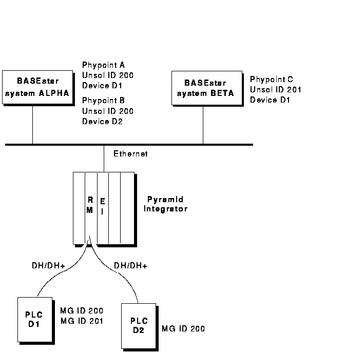
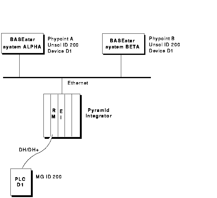
There is a restriction concerning the assignment of the unsolicited identifiers to DAS for AB INTERCHANGE software phypoints. The Ethernet Interface only allows one destination for an unsolicited ID. All messages coming from networked PLCs with a particular message ID are routed to only one destination on the TCP/IP network. If a INTERCHANGE application and a BASEstar Classic unsolicited point attempt to request data for the same ID, only one will be successful; the other will be returned with an error. The same is true for multiple BASEstar Classic systems. Only one BASEstar Classic system can use an unsolicited ID if they are going through the same Ethernet Interface. Figure 3_1 and Figure 3-2 show a valid and an invalid configuration.
Figure 3-1 Valid Unsolicited ID Configuration

Figure 3-1 illustrates a valid unsolicited configuration. The BASEstar Classic system ALPHA has two unsolicited physical points with the same unsolicited ID of 200 octal. The configuration is valid only because the two physical points are on different devices and their format and sizes are identical. BASEstar Classic system BETA also has a physical point from device D1; because of the restriction, however, a different unsolicited ID must be used.
Figure 3-2 Invalid Unsolicited ID Configuration

Figure 3-2 illustrates an invalid unsolicited configuration. Here both BASEstar Classic systems are attempting to use the same unsolicited ID (that both phypoints are on the same device is irrelevant). This is an invalid configuration because both BASEstar Classic systems need to route through the same Ethernet Interface module to access the unsolicited data.
| Previous | Next | Contents | Index |