| Previous | Contents | Index |
Qualification of new Fibre Channel hardware and larger configurations is ongoing. New hardware and larger configurations may necessitate enhancements to the Fibre Channel support in OpenVMS. Between releases of OpenVMS, enhancements and corrections to Fibre Channel software are made available by means of remedial kits on the HP support website.
The latest version of each kit is the one posted to the HP support web site. HP recommends that you monitor this web site.
HP also recommends that you monitor the Fibre Channel web site at:
http://h71000.www7.hp.com/openvms/fibre/
The Fibre Channel web site is periodically updated with important news
and new slide presentations.
7.2.2 Mixed-Version and Mixed-Architecture Cluster Support
Shared Fibre Channel OpenVMS Cluster storage is supported in both mixed-version and mixed-architecture OpenVMS Cluster systems. Mixed-version support is described in the Software Product Description. Mixed-architecture support means a combination of OpenVMS Alpha systems with OpenVMS Integrity server systems. In an OpenVMS mixed-architecture cluster, each architecture requires a minimum of one system disk.
The following configuration requirements must be observed:
This section presents example Fibre Channel configurations.
These configurations are valid for HSG storage controllers and for HSV storage controllers, except for Section 7.3.1 and Section 7.3.2, which apply only to HSG storage controllers. |
The configurations build on each other, starting with the smallest
valid configuration and adding redundant components for increasing
levels of availability, performance, and scalability.
7.3.1 Single Host with Dual-Ported Storage
Figure 7-4 shows a single system using Fibre Channel as a storage interconnect.
Figure 7-4 Single Host With One Dual-Ported Storage Controller
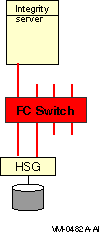
Note the following about this configuration:
Figure 7-5 shows multiple hosts connected to a dual-ported storage subsystem.
Figure 7-5 Multiple Hosts With One Dual-Ported Storage Controller
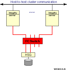
Note the following about this configuration:
7.3.3 Multiple Hosts With Storage Controller Redundancy
Figure 7-6 shows multiple hosts connected to two dual-ported storage
controllers.
Figure 7-6 Multiple Hosts With Storage Controller Redundancy
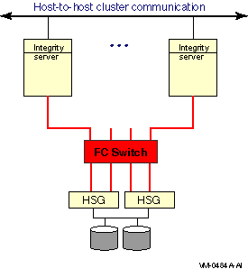
This configuration offers the following advantages:
7.3.4 Multiple Hosts With Multiple Independent Switches
Figure 7-7 shows multiple hosts connected to two switches, each of
which is connected to a pair of dual-ported storage controllers.
Figure 7-7 Multiple Hosts With Multiple Independent Switches
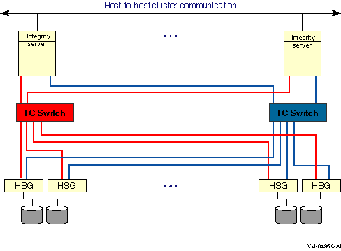
This two-switch configuration offers the advantages of the previous configurations plus the following:
7.3.5 Multiple Hosts With Dual Fabrics
Figure 7-8 shows multiple hosts connected to two fabrics; each
fabric consists of two switches.
Figure 7-8 Multiple Hosts With Dual Fabrics
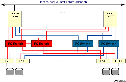
This dual-fabric configuration offers the advantages of the previous configurations plus the following advantages:
7.3.6 Multiple Hosts With Larger Fabrics
The configurations shown in this section offer even higher levels of
performance and scalability.
Figure 7-9 shows multiple hosts connected to two fabrics. Each fabric has four switches.
Figure 7-9 Multiple Hosts With Larger Dual Fabrics
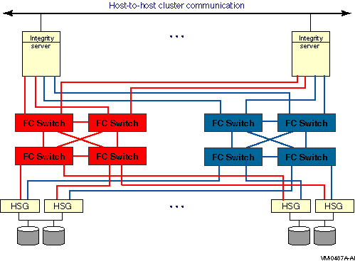
Figure 7-10 shows multiple hosts connected to four fabrics. Each fabric has four switches.
Figure 7-10 Multiple Hosts With Four Fabrics
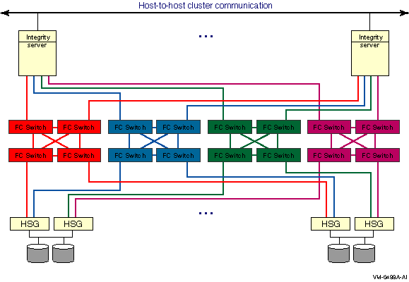
Fibre Channel devices for disk and tape storage come with
factory-assigned worldwide IDs (WWIDs). These WWIDs are used by the
system for automatic FC address assignment. The FC WWIDs and addresses
also provide the means for the system manager to identify and locate
devices in the FC configuration. The FC WWIDs and addresses are
displayed, for example, by the Alpha console and by the HSG or HSV
console. It is necessary, therefore, for the system manager to
understand the meaning of these identifiers and how they relate to
OpenVMS device names.
7.4.1 Fibre Channel Addresses and WWIDs
In most situations, Fibre Channel devices are configured to have temporary addresses. The device's address is assigned automatically each time the interconnect initializes. The device may receive a new address each time a Fibre Channel is reconfigured and reinitialized. This is done so that Fibre Channel devices do not require the use of address jumpers. There is one Fibre Channel address per port, as shown in Figure 7-11.
Figure 7-11 Fibre Channel Host and Port Addresses
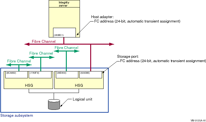
In order to provide more permanent identification, each port on each device has a WWID, which is assigned at the factory. Every Fibre Channel WWID is unique. Fibre Channel also has node WWIDs to identify multiported devices. WWIDs are used by the system to detect and recover from automatic address changes. They are useful to system managers for identifying and locating physical devices.
Figure 7-12 shows Fibre Channel components with their factory-assigned WWIDs and their Fibre Channel addresses.
Figure 7-12 Fibre Channel Host and Port WWIDs and Addresses
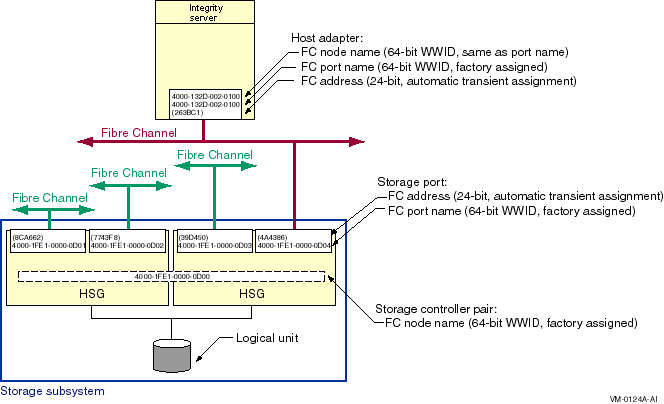
Note the following about this figure:
You can display the FC node name and FC port name for a Fibre Channel host bus adapter with the SHOW DEVICE/FULL command. For example:
$ SHOW DEVICE/FULL FGA0

Device FGA0:, device type KGPSA Fibre Channel, is online, shareable, error
    logging is enabled.

    Error count                    0    Operations completed                  0
    Owner process                 ""    Owner UIC                      [SYSTEM]
    Owner process ID        00000000    Dev Prot              S:RWPL,O:RWPL,G,W
    Reference count                0    Default buffer size                   0
    FC Port Name 1000-0000-C923-0E48    FC Node Name        2000-0000-C923-0E48
|
There is an OpenVMS name for each Fibre Channel storage adapter, for
each path from the storage adapter to the storage subsystem, and for
each storage device. These sections apply to both disk devices and tape
devices, except for Section 7.4.2.3, which is specific to disk devices.
Tape device names are described in Section 7.5.
7.4.2.1 Fibre Channel Storage Adapter Names
Fibre Channel storage adapter names, which are automatically assigned by OpenVMS, take the form FGx0 :
The naming design places a limit of 26 adapters per system. This naming may be modified in future releases to support a larger number of adapters.
Fibre Channel adapters can run multiple protocols, such as SCSI and LAN. Each protocol is a pseudodevice associated with the adapter. For the initial implementation, just the SCSI protocol is supported. The SCSI pseudodevice name is PGx0 , where x represents the same unit letter as the associated FGx0 adapter.
These names are illustrated in Figure 7-13.
Figure 7-13 Fibre Channel Initiator and Target Names
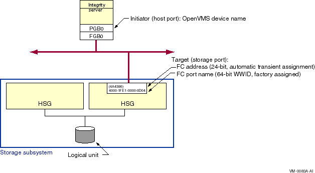
With the introduction of multipath SCSI support, as described in Chapter 6, it is necessary to identify specific paths from the host to the storage subsystem. This is done by concatenating the SCSI pseudodevice name, a decimal point (.), and the WWID of the storage subsystem port that is being accessed. For example, the Fibre Channel path shown in Figure 7-13 is named PGB0.4000-1FE1-0000-0D04.
Refer to Chapter 6 for more information on the display and use of
the Fibre Channel path name.
7.4.2.3 Fibre Channel Disk Device Identification
The four identifiers associated with each FC disk device are shown in Figure 7-14.
Figure 7-14 Fibre Channel Disk Device Naming
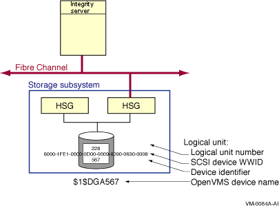
The logical unit number (LUN) is used by the system as the address of a specific device within the storage subsystem. This number is set and displayed from the HSG or HSV console by the system manager. It can also be displayed by the OpenVMS SDA utility.
Each Fibre Channel disk device also has a WWID to provide permanent, unique identification of the device. The HSG or HSV device WWID is 128 bits. Half of this identifier is the WWID of the HSG or HSV that created the logical storage device, and the other half is specific to the logical device. The device WWID is displayed by the SHOW DEVICE/FULL command, the HSG or HSV console and the AlphaServer console.
The third identifier associated with the storage device is a user-assigned device identifier. A device identifier has the following attributes:
The device identifier has a value of 567 in Figure 7-14. This value is used by OpenVMS to form the device name so it must be unique throughout the cluster. (It may be convenient to set the device identifier to the same value as the logical unit number (LUN). This is permitted as long as the device identifier is unique throughout the cluster.)
A Fibre Channel storage disk device name is formed by the operating system from the constant $1$DGA and a device identifier, nnnnn. Note that Fibre Channel disk device names use an allocation class value of 1 whereas Fibre Channel tape device names use an allocation class value of 2, as described in Section 7.5.2.1. The only variable part of the name is its device identifier, which you assign at the HSG or HSV console. Figure 7-14 shows a storage device that is known to the host as $1$DGA567.
A device identifier of 0 is not supported on the HSV. |
The following example shows the output of the SHOW DEVICE/FULL display for this device:
$ SHOW DEVICE/FULL $1$DGA567:

Disk $1$DGA567: (WILD8), device type HSG80, is online, mounted, file-oriented
    device, shareable, device has multiple I/O paths, served to cluster via MSCP
    Server, error logging is enabled.

    Error count                   14    Operations completed            6896599
    Owner process                 ""    Owner UIC                      [SYSTEM]
    Owner process ID        00000000    Dev Prot            S:RWPL,O:RWPL,G:R,W
    Reference count                9    Default buffer size                 512
    WWID   01000010:6000-1FE1-0000-0D00-0009-8090-0630-0008
    Total blocks            17769177    Sectors per track                   169
    Total cylinders             5258    Tracks per cylinder                  20
    Host name                "WILD8"    Host type, avail Compaq AlphaServer GS160 6/731, yes
    Alternate host name     "H2OFRD"    Alt. type, avail AlphaServer 1200 5/533 4MB, yes
    Allocation class               1

    Volume label      "S5SH_V72_SSS"    Relative volume number                0
    Cluster size                  18    Transaction count                     9
    Free blocks             12811860    Maximum files allowed            467609
    Extend quantity                5    Mount count                           6
    Mount status              System    Cache name          "_$1$DGA8:XQPCACHE"
    Extent cache size             64    Maximum blocks in extent cache  1281186
    File ID cache size            64    Blocks currently in extent cache1260738
    Quota cache size               0    Maximum buffers in FCP cache       1594
    Volume owner UIC           [1,1]    Vol Prot    S:RWCD,O:RWCD,G:RWCD,W:RWCD

  Volume Status:  ODS-2, subject to mount verification, file high-water marking,
      write-back XQP caching enabled, write-through XFC caching enabled.
  Volume is also mounted on H2OFRD, FIBRE3, NORLMN, BOOLA, FLAM10.

  I/O paths to device              5
  Path PGA0.5000-1FE1-0000-0D02  (WILD8), primary path.
    Error count                    0    Operations completed              14498
  Path PGA0.5000-1FE1-0000-0D03  (WILD8), current path.
    Error count                   14    Operations completed            6532610
  Path PGA0.5000-1FE1-0000-0D01  (WILD8).
    Error count                    0    Operations completed              14481
  Path PGA0.5000-1FE1-0000-0D04  (WILD8).
    Error count                    0    Operations completed              14481
  Path MSCP (H2OFRD).
    Error count                    0    Operations completed             320530
|
This section describes the configuration requirements and user commands
necessary to utilize the Fibre Channel tape functionality. Fibre
Channel tape functionality refers to the support of SCSI tapes and SCSI
tape libraries in an OpenVMS Cluster system with shared Fibre Channel
storage. The SCSI tapes and libraries are connected to the Fibre
Channel by a Fibre-to-SCSI bridge. Currently, two bridges are
available: the Modular Data Router (MDR) and the Network Storage Router
(NSR).
7.5.1 Minimum Hardware Configuration
Following is the minimum Fibre Channel tape hardware configuration:
Tapes are not supported in an HSGxx storage subsystem nor behind a Fibre Channel Tape Controller II (FCTC-II). A tape library robot is an example of a medium changer device, the term that is used throughout this section. |
This section provides detailed background information about Fibre Channel Tape device naming.
Tape and medium changer devices are automatically named and configured
using the SYSMAN IO FIND and IO AUTOCONFIGURE commands described in
Section 7.5.3. System managers who configure tapes on Fibre Channel
should refer directly to this section for the tape configuration
procedure.
7.5.2.1 Tape and Medium Changer Device Names
Fibre Channel tapes and medium changers are named using a scheme similar to Fibre Channel disk naming.
On parallel SCSI, the device name of a directly attached tape implies the physical location of the device; for example, MKB301 resides on bus B, SCSI target ID 3, and LUN 1. Such a naming scheme does not scale well for Fibre Channel configurations, in which the number of targets or nodes can be very large.
Fibre Channel tape names are in the form $2$MGAn. The letter for the controller is always A, and the prefix is $2$. The device mnemonic is MG for tapes and GG for medium changers. The device unit n is automatically generated by OpenVMS.
The name creation algorithm chooses the first free unit number, starting with zero. The first tape discovered on the Fibre Channel is named $2$MGA0, the next is named $2$MGA1, and so forth. Similarly, the first medium changer detected on the Fibre Channel is named $2$GGA0. The naming of tapes and medium changers on parallel SCSI buses remains the same.
Note the use of allocation class 2. Allocation class 1 is already used by devices whose name is keyed by a user-defined identifier (UDID), as with HSG Fibre Channel disks ($1$DGAnnnn) and HSG console command LUNs ($1$GGAnnnn).
An allocation class of 2 is used by devices whose names are obtained from the file, SYS$DEVICES.DAT. The names are based on a worldwide identifier (WWID) key, as described in the following sections. Also note that, while GG is the same mnemonic used for both medium changers and HSG Command Console LUNs (CCLs), medium changers always have an allocation class of 2 and HSG CCLs an allocation class of 1.
Tape and medium changer names are automatically kept consistent within a single OpenVMS Cluster system. Once a tape device is named by any node in the cluster, all other nodes in the cluster automatically choose the same name for that device, even if this overrides the first free unit number algorithm. The chosen device name remains the same through all subsequent reboot operations in the cluster.
If multiple nonclustered Integrity server systems exist on a SAN and
need to access the same tape device on the Fibre Channel, then the
upper-level application must provide consistent naming and synchronized
access.
7.5.2.2 Use of Worldwide Identifiers (WWIDs)
For each Fibre Channel tape device name, OpenVMS must uniquely identify the physical device that is associated with that name.
In parallel SCSI, directly attached devices are uniquely identified by their physical path (port/target/LUN). Fibre Channel disks are uniquely identified by user-defined identifiers (UDIDs). These strategies are either unscalable or unavailable for Fibre Channel tapes and medium changers.
Therefore, the identifier for a given Fibre Channel tape or medium changer device is its worldwide identifier (WWID). The WWID resides in the device firmware and is required to be unique by the Fibre Channel standards.
WWIDs can take several forms, for example:
The overall WWID consists of the WWID data prefixed by a binary WWID header, which is a longword describing the length and type of WWID data.
In general, if a device reports an IEEE WWID, OpenVMS chooses this as the unique identifying WWID for the device. If the device does not report such a WWID, then the ASCII WWID is used. If the device reports neither an IEEE WWID nor serial number information, then OpenVMS does not configure the device. During the device discovery process, OpenVMS rejects the device with the following message:
%SYSMAN-E-NOWWID, error for device Product-ID, no valid WWID found. |
The WWID structures can be a mix of binary and ASCII data. These formats are displayable and are intended to be consistent with those defined by the console WWIDMGR utility. Refer to the Wwidmgr Users' Manual for additional information. (The Wwidmgr Users' Manual is available in the [.DOC] directory of the Alpha Systems Firmware Update CD-ROM.)
Note that if the data following the WWID header is pure ASCII data, it must be enclosed in double quotation marks.
The displayable format of a 64-bit IEEE WWID consists of an 8-digit hexadecimal number in ASCII (the WWID header), followed by a colon (:) and then the IEEE WWID data. For example:
0C000008:0800-4606-8010-CD3C |
The displayable format of an ASCII WWID consists of an 8-digit WWID header, followed by a colon (:) and then the concatenation of the 8-byte vendor ID plus the 16-byte product ID plus the serial number. For example:
04100022:"COMPAQ DLT8000 JF71209240" |
Occasionally, an ASCII WWID may contain nonprintable characters in the serial number. In a displayable format, such a character is represented by\nn, where nn is the 2-digit ASCII hexadecimal value of the character. For example, a null is represented by\00. |
| Previous | Next | Contents | Index |