| Previous | Contents | Index |
Table 8-3 shows a variety of related OpenVMS Cluster software products that HP offers to increase availability.
| Product | Description |
|---|---|
| Availability Manager | Collects and analyzes data from multiple nodes simultaneously and directs all output to a centralized DECwindows display. The analysis detects availability problems and suggests corrective actions. |
| RTR | Provides continuous and fault-tolerant transaction delivery services in a distributed environment with scalability and location transparency. In-flight transactions are guaranteed with the two-phase commit protocol, and databases can be distributed worldwide and partitioned for improved performance. |
| Volume Shadowing for OpenVMS | Makes any disk in an OpenVMS Cluster system a redundant twin of any other same-size disk (same number of physical blocks) in the OpenVMS Cluster. |
The hardware you choose and the way you configure it has a significant
impact on the availability of your OpenVMS Cluster system. This section
presents strategies for designing an OpenVMS Cluster configuration that
promotes availability.
8.3.1 Availability Strategies
Table 8-4 lists strategies for configuring a highly available OpenVMS Cluster. These strategies are listed in order of importance, and many of them are illustrated in the sample optimal configurations shown in this chapter.
| Strategy | Description |
|---|---|
| Eliminate single points of failure | Make components redundant so that if one component fails, the other is available to take over. |
| Shadow system disks | The system disk is vital for node operation. Use Volume Shadowing for OpenVMS to make system disks redundant. |
| Shadow essential data disks | Use Volume Shadowing for OpenVMS to improve data availability by making data disks redundant. |
| Provide shared, direct access to storage | Where possible, give all nodes shared direct access to storage. This reduces dependency on MSCP server nodes for access to storage. |
| Minimize environmental risks |
Take the following steps to minimize the risk of environmental problems:
|
| Configure at least three nodes |
OpenVMS Cluster nodes require a quorum to continue operating. An
optimal configuration uses a minimum of three nodes so that if one node
becomes unavailable, the two remaining nodes maintain quorum and
continue processing.
Reference: For detailed information on quorum strategies, see Section 10.5 and HP OpenVMS Cluster Systems. |
| Configure extra capacity | For each component, configure at least one unit more than is necessary to handle capacity. Try to keep component use at 80% of capacity or less. For crucial components, keep resource use sufficiently less than 80% capacity so that if one component fails, the work load can be spread across remaining components without overloading them. |
| Keep a spare component on standby | For each component, keep one or two spares available and ready to use if a component fails. Be sure to test spare components regularly to make sure they work. More than one or two spare components increases complexity as well as the chance that the spare will not operate correctly when needed. |
| Use homogeneous nodes | Configure nodes of similar size and performance to avoid capacity overloads in case of failover. If a large node fails, a smaller node may not be able to handle the transferred work load. The resulting bottleneck may decrease OpenVMS Cluster performance. |
| Use reliable hardware | Consider the probability of a hardware device failing. Check product descriptions for MTBF (mean time between failures). In general, newer technologies are more reliable. |
Achieving high availability is an ongoing process. How you manage your
OpenVMS Cluster system is just as important as how you configure it.
This section presents strategies for maintaining availability in your
OpenVMS Cluster configuration.
8.4.1 Strategies for Maintaining Availability
After you have set up your initial configuration, follow the strategies listed in Table 8-5 to maintain availability in OpenVMS Cluster system.
| Strategy | Description |
|---|---|
| Plan a failover strategy |
OpenVMS Cluster systems provide software support for failover between
hardware components. Be aware of what failover capabilities are
available and which can be customized for your needs. Determine which
components must recover from failure, and make sure that components are
able to handle the additional work load that may result from a failover.
Reference: Table 8-2 lists OpenVMS Cluster failover mechanisms and the levels of recovery that they provide. |
| Code distributed applications | Code applications to run simultaneously on multiple nodes in an OpenVMS Cluster system. If a node fails, the remaining members of the OpenVMS Cluster system are still available and continue to access the disks, tapes, printers, and other peripheral devices that they need. |
| Minimize change | Assess carefully the need for any hardware or software change before implementing it on a running node. If you must make a change, test it in a noncritical environment before applying it to your production environment. |
| Reduce size and complexity | After you have achieved redundancy, reduce the number of components and the complexity of the configuration. A simple configuration minimizes the potential for user and operator errors as well as hardware and software errors. |
| Set polling timers identically on all nodes |
Certain system parameters control the polling timers used to maintain
an OpenVMS Cluster system. Make sure these system parameter values are
set identically on all OpenVMS Cluster member nodes.
Reference: For information about these system parameters, refer to HP OpenVMS Cluster Systems. |
| Manage proactively | The more experience your system managers have, the better. Allow privileges for only those users or operators who need them. Design strict policies for managing and securing the OpenVMS Cluster system. |
| Use AUTOGEN proactively | With regular AUTOGEN feedback, you can analyze resource usage that may affect system parameter settings. |
| Reduce dependencies on a single server or disk | Distributing data across several systems and disks prevents one system or disk from being a single point of failure. |
| Implement a backup strategy | Performing frequent backup procedures on a regular basis guarantees the ability to recover data after failures. None of the strategies listed in this table can take the place of a solid backup strategy. |
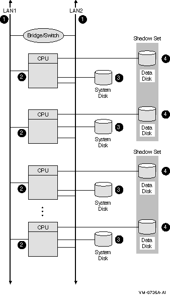
Figure 8-1 shows an optimal configuration for a small-capacity, highly available LAN OpenVMS Cluster system. Figure 8-1 is followed by an analysis of the configuration that includes:
Figure 8-1 LAN OpenVMS Cluster System
8.5.1 Components
The LAN OpenVMS Cluster configuration in Figure 8-1 has the
following components:
| Component | Description |
|---|---|
| 1 |
Two Ethernet interconnects. For higher network capacity, use Gigabit
Ethernet or 10 Gigabit Ethernet.
Rationale: For redundancy, use at least two LAN interconnects and attach all nodes to all LAN interconnects. A single interconnect would introduce a single point of failure. |
| 2 |
Three to eight Ethernet-capable OpenVMS nodes.
Each node has its own system disk so that it is not dependent on another node. Rationale: Use at least three nodes to maintain quorum. Use fewer than eight nodes to avoid the complexity of managing eight system disks. Alternative 1: If you require satellite nodes, configure one or two nodes as boot servers. Note, however, that the availability of the satellite nodes is dependent on the availability of the server nodes. Alternative 2: For more than eight nodes, use a LAN OpenVMS Cluster configuration as described in Section 8.9. |
| 3 |
System disks.
System disks generally are not shadowed in LAN OpenVMS Clusters because of boot-order dependencies. Alternative 1: Shadow the system disk across two local controllers. Alternative 2: Shadow the system disk across two nodes. The second node mounts the disk as a nonsystem disk. Reference: See Section 10.2.4 for an explanation of boot-order and satellite dependencies. |
| 4 |
Essential data disks.
Use volume shadowing to create multiple copies of all essential data disks. Place shadow set members on at least two nodes to eliminate a single point of failure. |
This configuration offers the following advantages:
This configuration has the following disadvantages:
The configuration in Figure 8-1 incorporates the following strategies, which are critical to its success:
Follow these guidelines to configure a highly available multiple LAN cluster:
Reference: See Section 9.3.8 for information about
extended LANs (ELANs). For differences between Alpha and Integrity
server satellites, see the OpenVMS Cluster Systems Guide.
8.6.1 Selecting MOP Servers
When using multiple LAN adapters with multiple LAN segments, distribute the connections to LAN segments that provide MOP service. The distribution allows MOP servers to downline load satellites even when network component failures occur.
It is important to ensure sufficient MOP servers for both Alpha and Integrity server nodes to provide downline load support for booting satellites. By careful selection of the LAN connection for each MOP server (Alpha or VAX, as appropriate) on the network, you can maintain MOP service in the face of network failures.
8.6.2 Configuring Two LAN Segments
Figure 8-2 shows a sample configuration for an OpenVMS Cluster
system connected to two different LAN segments. The configuration
includes Integrity server and Alpha nodes, satellites, and two bridges.
Figure 8-2 Two-LAN Segment OpenVMS Cluster Configuration
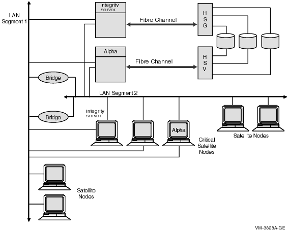
The figure illustrates the following points:
Figure 8-3 shows a sample configuration for an OpenVMS Cluster system connected to three different LAN segments. The configuration also includes both Alpha and Integrity server nodes, satellites and multiple bridges.
Figure 8-3 Three-LAN Segment OpenVMS Cluster Configuration
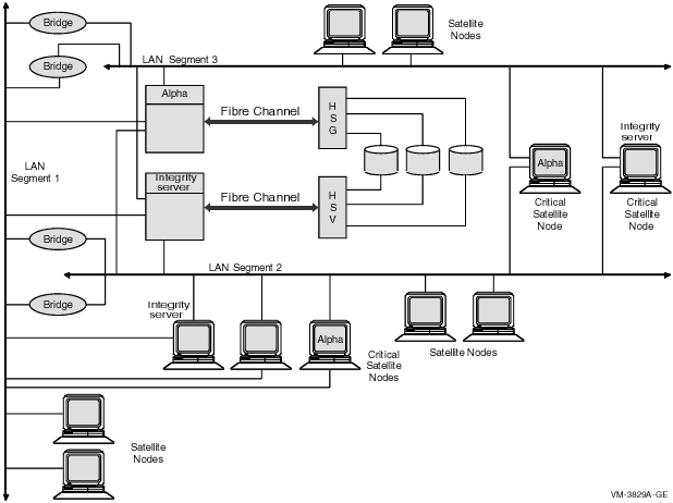
The figure illustrates the following points:
Reference: See Section 10.2.4 for more information
about boot order and satellite dependencies in a LAN. See HP OpenVMS Cluster Systems
for information about LAN bridge failover.
8.7 Availability in a Cluster over IP
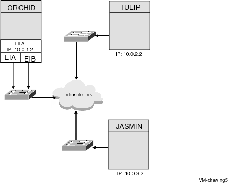
Figure 8-4 shows an optimal configuration for a medium-capacity, highly available Logical LAN Failover IP OpenVMS Cluster system. Figure 8-4 is followed by an analysis of the configuration that includes:
Figure 8-4 Logical LAN Failover IP OpenVMS Cluster System
8.7.1 Components
The IP OpenVMS Cluster configuration in Figure 8-4 has the following
components:
| Part | Description |
|---|---|
| 1 |
EIA and EIB are the two IP interfaces connected to the node
Rationale: Both the interfaces must be used to connect
to the node for availability. EIA and EIB are the two LAN interfaces
connected to the node. The two LAN interfaces can be used to create a
Logical LAN failover set. Execute the following command to create a
logical LAN failover set:
IP addresses can be configured on the Logical LAN failover device and can be used for cluster communication. |
| 2 |
Intersite Link
Rationale: Multiple intersite links can be obtained from either the same vendor or two different vendors ensuring site-to-site high availability. |
The configuration in Figure 8-4 offers the following advantages:
The configuration in Figure 8-4 incorporates the following strategies, which are critical to its success:
$ MC LANCP LANCP> DEFINE DEVICE LLB/ENABLE/FAILOVER=(EIA0, EIB0) |
8.8 Availability in a MEMORY CHANNEL OpenVMS Cluster
Figure 8-5 shows a highly available MEMORY CHANNEL (MC) cluster
configuration. Figure 8-5 is followed by an analysis of the
configuration that includes:
Figure 8-5 MEMORY CHANNEL Cluster
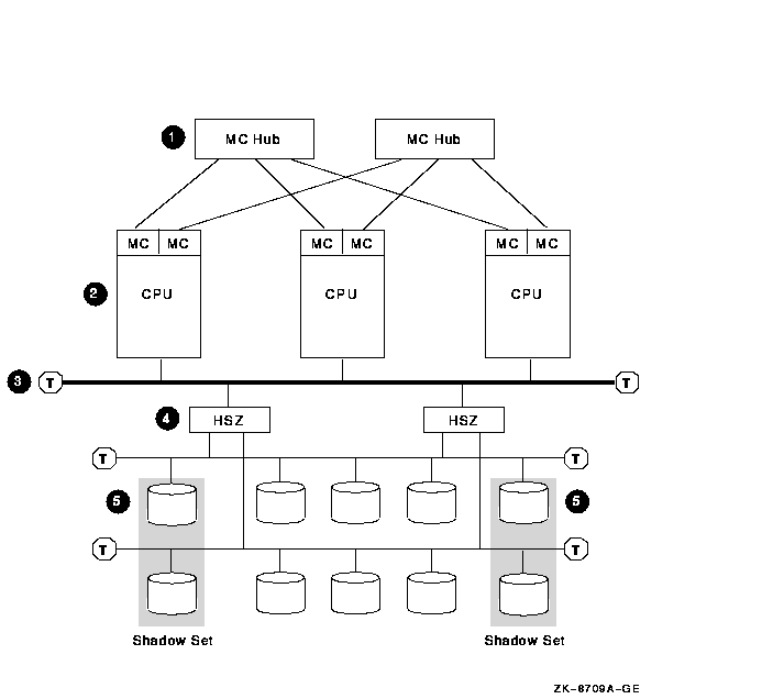
The MEMORY CHANNEL configuration shown in Figure 8-5 has the following components:
| Part | Description |
|---|---|
| 1 |
Two MEMORY CHANNEL hubs.
Rationale: Having two hubs and multiple connections to the nodes prevents having a single point of failure. |
| 2 |
Three to eight MEMORY CHANNEL nodes.
Rationale: Three nodes are recommended to maintain quorum. A MEMORY CHANNEL interconnect can support a maximum of eight OpenVMS Alpha nodes. Alternative: Two-node configurations require a quorum disk to maintain quorum if a node fails. |
| 3 |
Fast-wide differential (FWD) SCSI bus.
Rationale: Use a FWD SCSI bus to enhance data transfer rates (20 million transfers per second) and because it supports up to two HSZ controllers. |
| 4 |
Two HSZ controllers.
Rationale: Two HSZ controllers ensure redundancy in case one of the controllers fails. With two controllers, you can connect two single-ended SCSI buses and more storage. |
| 5 |
Essential system disks and data disks.
Rationale: Shadow essential disks and place shadow set members on different SCSI buses to eliminate a single point of failure. |
| Previous | Next | Contents | Index |