| Previous | Contents | Index |
The ability to create a logical LAN failover set using IP for cluster
communication provides high availability systems. The nodes will be
able to resume if a local LAN card fails, as it will switchover to
another interface configured in the logical LAN failover set. For a
complete description of creating a logical LAN failover set, see
Guidelines for OpenVMS Cluster Configurations. The hardware
dependency on the LAN bridge is also overcome by GbE switches or
routers used for transmission and forwarding the information.
3.3.3 System Characteristics
The existing functionalities of OpenVMS Clusters continue to exist with IP interconnect. Cluster over IP has the following characteristics:
The following software is required to support Clusters over IP interconnect:
Ensure that the TCP/IP software is configured before configuring Cluster over IP. To ensure that network and TCP/IP is configured properly, use the PING utility and ping the node from outside the subnet. |
IP Multicast Address
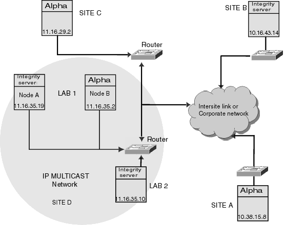
PEDRIVER uses 802 multicast for discovering cluster members in a LAN. IP multicast maps 1:1 onto the existing LAN discovery, and hence, has been selected as the preferred mechanism to discover nodes in a cluster. Every cluster using IP multicast will have one IP multicast address unique for that cluster. Multicast address is also used for keep-alive mechanism. Administratively scoped IP multicast address is used for cluster communication.
IP Unicast Address
Unicast address can be used if IP multicast is not enabled in a network. Remote node IP address must be present in the local node configuration files to allow the remote node to join the cluster. As a best practice, include all IP addresses and maintain one copy of the file throughout the cluster. $MC SCACP RELOAD can be used to refresh IP unicast list on a live system.
NISCS_USE_UDP SYSGEN Parameter
This parameter is set to enable the Cluster over IP functionality. PEDRIVER will use the UDP protocol in addition to IEEE 802.3 for cluster communication. CLUSTER_CONFIG_LAN is used to enable cluster over IP which will set this SYSGEN parameter.
UDP Port Number
UDP port number can be configured using CLUSTER_CONFIG_LAN and is constant in all nodes of a cluster.
Standard internet practice such as firewall could be applied based on the port number that is selected for cluster. |
SYS$SYSTEM:PE$IP_CONFIG.DAT and SYS$SYSTEM:TCPIP$CLUSTER.DAT are the two configuration files . These files are loaded during the boot process and provide the necessary configuration details for Cluster over IP. Both these files are generated when a node is configured to be a member of the cluster and if cluster over IP is enabled during the configuration.
SYS$SYSTEM:PE$IP_CONFIG.DAT includes the optional IP multicast and IP unicast addresses of the nodes of the cluster. IP multicast messages are used for discovering a node within the same IP multicast domain. Remote nodes in a different IP multicast domain can use the IP unicast messaging technique to join the cluster. SYS$SYSTEM:PE$IP_CONFIG.DAT can be common for all the nodes of a cluster.
SYS$SYSTEM:TCPIP$CLUSTER.DAT contains the IP interface name and IP
addresses on which cluster communication is enabled. It also includes
the TCP/IP route information. SYS$SYSTEM:TCPIP$CLUSTER.DAT is unique
for each node in a cluster.
3.3.6 Satellite Node Support
Integrity server satellite node support
The Integrity server satellite node must be in the same LAN on which the boot server resides. The Alpha satellite node must be in the same LAN as its disk server.
Alpha satellite node support
The Alpha console uses the MOP protocol for network load of satellite
systems. Because the MOP protocol is non-routable, the satellite boot
server or servers and all satellites booting from them must reside in
the same LAN. In addition, the boot server must have at least one LAN
device enabled for cluster communications to permit the Alpha satellite
nodes to access the system disk.
3.3.7 High Availability Configuration using Logical LAN
The ability to create a logical LAN failover set and using IP for
cluster communication with the logical LAN failover set provides high
availability and can withstand NIC failure to provide high availability
configuration. The nodes will be able to continue to communicate even
if a local LAN card fails, as it will switchover to another interface
configured in the logical LAN failover set. For a complete description
of creating a logical LAN failover set and using it for Cluster over
IP, see Guidelines for OpenVMS Cluster Configurations. For an example
on how to create and configure a Logical LAN failover, refer to
Scenario 5: Configuring an Integrity server Node Using a Logical LAN
Failover set.
3.3.8 Performance Guidelines
The TCP/IP stack overhead is considered to be in µs because of the additional layer used for cluster communication. As distance increases this overhead becomes negligible compared to the latency of speed of light. Multi site cluster can leverage from Cluster over IP feature. FASTPATH CPU configuration is recommended for better performance. LAN, TCP/IP and PE device must be on a single CPU. Ensure that there is headroom in the CPU and the CPU is not saturated.
Fastpath configuration is not applicable for BG devices when (Packet Processing Engine) PPE is enabled. BG device always takes the primary CPU when cluster over IP is configured and if TCP/IP stack is loaded. It is required to move the BG device to an appropriate CPU using the $SET DEVICE/PREFERRED command. |
Figure 3-5 OpenVMS Cluster Configuration Based on IP
MEMORY CHANNEL is a high-performance cluster interconnect technology
for PCI-based Alpha systems. With the benefits of very low latency,
high bandwidth, and direct memory access, MEMORY CHANNEL complements
and extends the ability of OpenVMS Clusters to work as a single virtual
system. MEMORY CHANNEL is used for node-to-node cluster communications
only. You use it in combination with another interconnect, such as
Fibre Channel, SCSI, CI, or DSSI, that is dedicated to storage traffic.
3.4.1 Design
A node requires the following three hardware components to support a MEMORY CHANNEL connection:
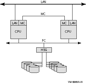
Figure 3-6 shows a two-node MEMORY CHANNEL cluster with shared access to Fibre Channel storage and a LAN interconnect for failover.
Figure 3-6 Two-Node MEMORY CHANNEL OpenVMS Cluster Configuration
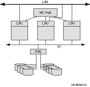
A three-node MEMORY CHANNEL cluster connected by a MEMORY CHANNEL hub and also by a LAN interconnect is shown in Figure 3-7. The three nodes share access to the Fibre Channel storage. The LAN interconnect enables failover if the MEMORY CHANNEL interconnect fails.
Figure 3-7 Three-Node MEMORY CHANNEL OpenVMS Cluster Configuration
A mixed-interconnect OpenVMS Cluster system is any OpenVMS Cluster system that uses more than one interconnect for SCS communication. You can use mixed interconnects to combine the advantages of each type and to expand your OpenVMS Cluster system. For example, an Ethernet cluster that requires more storage can expand with the addition of Fibre Channel, SCSI, or SAS connections.
If any one node in a cluster requires IP for cluster communication, all the other members in the cluster must be enabled for IP cluster communication. |
OpenVMS Cluster systems using a mix of interconnects provide maximum
flexibility in combining CPUs, storage, and workstations into highly
available configurations.
3.5.2 Examples
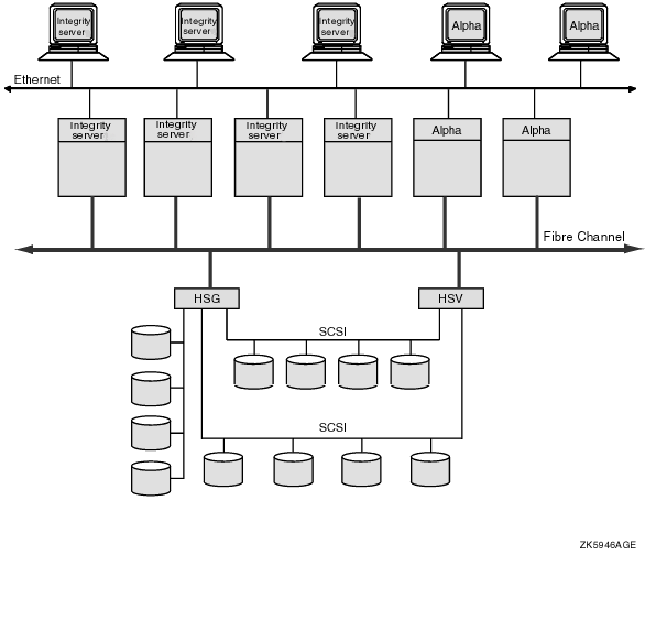
Figure 3-8 shows a mixed-interconnect OpenVMS Cluster system using both FC and Ethernet interconnects.
The computers based on the FC can serve HSG or HSV disks to the satellite nodes by means of MSCP server software and drivers; therefore, satellites can access the large amount of storage that is available through HSG and HSV subsystems.
Figure 3-8 OpenVMS Cluster System Using FC and Ethernet Interconnects
OpenVMS Cluster systems support the SCSI as a storage interconnect. A SCSI interconnect, also called a SCSI bus, is an industry-standard interconnect that supports one or more computers, peripheral devices, and interconnecting components.
Beginning with OpenVMS Alpha Version 6.2, multiple Alpha computers using the KZPBA SCSI host-based adapter, can simultaneously access SCSI disks over a SCSI interconnect. Another interconnect, for example, a local area network, is required for host-to-host OpenVMS cluster communications. On Alpha computers, this support is limited to the KZPBA adapter. Newer SCSI host-based adapters for Alpha computers support only directly attached SCSI storage.
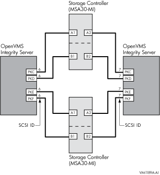
Beginning with OpenVMS Version 8.2-1, support is available for shared SCSI storage in a two-node OpenVMS Integrity server systems configuration using the MSA30-MI storage shelf.
Shared SCSI storage in an OpenVMS Cluster system enables computers
connected to a single SCSI bus to share access to SCSI storage devices
directly. This capability makes it possible to build highly available
servers using shared access to SCSI storage.
3.6.1 Design for OpenVMS Alpha Configurations
Beginning with OpenVMS Alpha Version 6.2-1H3, OpenVMS Alpha supports up to three nodes on a shared SCSI bus as the storage interconnect. A quorum disk can be used on the SCSI bus to improve the availability of two-node configurations. Host-based RAID (including host-based shadowing) and the MSCP server are supported for shared SCSI storage devices.
Using the SCSI hub DWZZH-05, four nodes can be supported in a SCSI multihost OpenVMS Cluster system. In order to support four nodes, the hub's fair arbitration feature must be enabled.
For a complete description of these configurations, see Guidelines for OpenVMS Cluster Configurations.
3.6.2 Design for OpenVMS Integrity server Configurations
Shared SCSI storage in an OpenVMS Integrity server Cluster system is subject to the following restrictions:
In Figure 3-10 the SCSI IDs of 6 and 7, are required in this configuration. One of the systems must have a SCSI ID of 6 for each A7173A adapter port connected to a shared SCSI bus, instead of the factory-set default of 7. You can use the U320_SCSI pscsi.efi utility, included in the IPF Offline Diagnostics and Utilities CD, to change the SCSI ID. The procedure for doing this is documented in the HP A7173A PCI-X Dual Channel Ultra320 SCSI Host Bus Adapter Installation Guide, is available at:
http://docs.hp.com/en/netcom.html |
3.6.3 Examples
Figure 3-9 shows an OpenVMS Cluster configuration that uses a SCSI
interconnect for shared access to SCSI devices. Note that another
interconnect, a LAN in this example, is used for host-to-host
communications.
Figure 3-9 Three-Node OpenVMS Cluster Configuration Using a Shared SCSI Interconnect
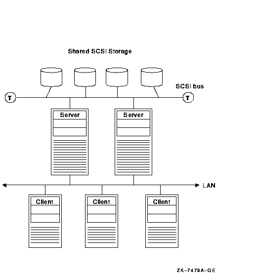
Figure 3-10 illustrates the two-node OpenVMS Integrity server configuration. Note that a second interconnect, a LAN, is required for host-to-host OpenVMS Cluster communications. (OpenVMS Cluster communications are also known as SCA (System Communications Architecture) communications.)
Figure 3-10 Two-Node OpenVMS Integrity server Cluster System
OpenVMS Cluster systems support SAS as a storage interconnect. SAS is a point-to-point architecture that transfers data to and from SCSI storage devices by using serial communication (one bit at a time). SAS uses the SAS devices and differential signaling method to achieve reliable, high-speed serial communication.
SAS combines high-end features from fiber channel (such as multi-initiator support and full duplex communication) and the physical interface leveraged from SATA (for better compatibility and investment protection), with the performance, reliability and ease of use of traditional SCSI technology.
3.8 Multihost Fibre Channel OpenVMS Cluster Systems
OpenVMS Cluster systems support FC interconnect as a storage
interconnect. Fibre Channel is an ANSI standard network and storage
interconnect that offers many advantages over other interconnects,
including high-speed transmission and long interconnect distances. A
second interconnect is required for node-to-node communications.
3.8.1 Design
OpenVMS Alpha supports the Fibre Channel SAN configurations described in the latest HP StorageWorks SAN Design Reference Guide (order number AA-RMPNT-TE) and in the Data Replication Manager (DRM) user documentation. This configuration support includes multiswitch Fibre Channel fabrics, up to 500 meters of multimode fiber, and up to 100 kilometers of single-mode fiber. In addition, DRM configurations provide long-distance intersite links (ISLs) through the use of the Open Systems Gateway and wave division multiplexors. OpenVMS supports sharing of the fabric and the HSG storage with non-OpenVMS systems.
OpenVMS provides support for the number of hosts, switches, and storage controllers specified in the StorageWorks documentation. In general, the number of hosts and storage controllers is limited only by the number of available fabric connections.
Host-based RAID (including host-based shadowing) and the MSCP server are supported for shared Fibre Channel storage devices. Multipath support is available for these configurations.
For a complete description of these configurations, see Guidelines for OpenVMS Cluster Configurations.
This chapter describes how to prepare the OpenVMS Cluster operating
environment.
4.1 Preparing the Operating Environment
To prepare the cluster operating environment, there are a number of steps you perform on the first OpenVMS Cluster node before configuring other computers into the cluster. The following table describes these tasks.
| Task | Section |
|---|---|
| Check all hardware connections to computer, interconnects, and devices. | Described in the appropriate hardware documentation. |
| Verify that all microcode and hardware is set to the correct revision levels. | Contact your support representative. |
| Install the OpenVMS operating system. | Section 4.2 |
| Install all software licenses, including OpenVMS Cluster licenses. | Section 4.3 |
| Install layered products. | Section 4.4 |
| Configure and start LANCP or DECnet for satellite booting | Section 4.5 |
Only one OpenVMS operating system version can exist on a system disk. Therefore, when installing or upgrading the OpenVMS operating systems ensure that you:
Mixed architecture clusters of either OpenVMS Integrity server systems and OpenVMS Alpha systems are supported. |
A system disk is one of the few resources that cannot be shared between Integrity and Alpha systems.
Once booted, Integrity server systems and Alpha systems can share access to data on any disk in the OpenVMS Cluster, including system disks. For example, an Integrity server system can mount an Alpha system disk as a data disk and an Alpha system can mount an Integrity server system disk as a data disk.
An OpenVMS Cluster running both implementations of DECnet requires a system disk for DECnet for OpenVMS (Phase IV) and another system disk for DECnet-Plus (Phase V). For more information, see the DECnet-Plus documentation. |
You might want to set up common system disks according to these guidelines:
| IF you want the cluster to have... | THEN perform the installation or upgrade... |
|---|---|
| One common system disk for all computer members | Once on the cluster common system disk. |
| A combination of one or more common system disks and one or more local (individual) system disks |
|
|
Note: If your cluster includes multiple common system
disks, you must later coordinate system files to define the cluster
operating environment, as described in Chapter 5.
Reference: See Section 8.5 for information about creating a duplicate system disk. |
|
Example: If your OpenVMS Cluster consists of 10
computers, four of which boot from a common Integrity server system
disk, two of which boot from a second common Integrity system disk, two
of which boot from a common Alpha system disk, and two of which boot
from their own local system disk, you need to perform an installation
five times.
4.2.3 Information Required
Table 4-1 table lists the questions that the OpenVMS operating system installation procedure prompts you with and describes how certain system parameters are affected by responses you provide. You will notice that two of the prompts vary, depending on whether the node is running DECnet. The table also provides an example of an installation procedure that is taking place on a node named JUPITR.
Important: Be sure you determine answers to the questions before you begin the installation.
Note about versions: Refer to the appropriate OpenVMS OpenVMS Release Notes document for the required version numbers of hardware and firmware. When mixing versions of the operating system in an OpenVMS Cluster, check the release notes for information about compatibility.
Reference: Refer to the appropriate OpenVMS upgrade and installation manual for complete installation instructions.
| Prompt | Response | Parameter | ||||||||||||
|---|---|---|---|---|---|---|---|---|---|---|---|---|---|---|
| Will this node be a cluster member (Y/N)? |
|
VAXCLUSTER | ||||||||||||
| What is the node's DECnet node name? | If the node is running DECnet, this prompt, the following prompt, and the SCSSYSTEMID prompt are displayed. Enter the DECnet node name or the DECnet--Plus node synonym (for example, JUPITR). If a node synonym is not defined, SCSNODE can be any name from 1 to 6 alphanumeric characters in length. The name cannot include dollar signs ($) or underscores (_). | SCSNODE | ||||||||||||
| What is the node's DECnet node address? |
Enter the DECnet node address (for example, a valid address might be
2.211). If an address has not been assigned, enter 0 now and enter a
valid address when you start DECnet (discussed later in this chapter).
For DECnet--Plus, this question is asked when nodes are configured with a Phase IV compatible address. If a Phase IV compatible address is not configured, then the SCSSYSTEMID system parameter can be set to any value. |
SCSSYSTEMID | ||||||||||||
| What is the node's SCS node name? | If the node is not running DECnet, this prompt and the following prompt are displayed in place of the two previous prompts. Enter a name of 1 to 6 alphanumeric characters that uniquely names this node. At least 1 character must be a letter. The name cannot include dollar signs ($) or underscores (_). | SCSNODE | ||||||||||||
| What is the node's SCSSYSTEMID number? |
This number must be unique within this cluster. SCSSYSTEMID is the
low-order 32 bits of the 48-bit system identification number.
If the node is running DECnet for OpenVMS, calculate the value from the DECnet address using the following formula: SCSSYSTEMID = ( DECnet-area-number * 1024) + ( DECnet-node-number)
Example: If the DECnet address is 2.211, calculate the
value as follows:
|
SCSSYSTEMID | ||||||||||||
| Will the Ethernet be used for cluster communications (Y/N)? |
|
NISCS_LOAD_PEA0 | ||||||||||||
| Will the IP interconnect be used for cluster communications (Y/N)? |
|
NISCS_USE_UDP | ||||||||||||
| Enter this cluster's group number: | Enter a number in the range of 1 to 4095 or 61440 to 65535 (see Section 2.5). This value is stored in the CLUSTER_AUTHORIZE.DAT file in the SYS$COMMON:[SYSEXE] directory. | Not applicable | ||||||||||||
| Enter this cluster's password: | Enter the cluster password. The password must be from 1 to 31 alphanumeric characters in length and can include dollar signs ($) and underscores (_) (see Section 2.5). This value is stored in scrambled form in the CLUSTER_AUTHORIZE.DAT file in the SYS$COMMON:[SYSEXE] directory. | Not applicable | ||||||||||||
| Reenter this cluster's password for verification: | Reenter the password. | Not applicable | ||||||||||||
| Will JUPITR be a disk server (Y/N)? |
|
MSCP_LOAD | ||||||||||||
| Will JUPITR serve HSC or RF disks (Y/N)? |
|
MSCP_SERVE_ALL | ||||||||||||
| Enter a value for JUPITR's ALLOCLASS parameter: 2 |
The value is dependent on the system configuration:
|
ALLOCLASS | ||||||||||||
| Does this cluster contain a quorum disk [N]? | Enter Y or N, depending on your configuration. If you enter Y, the procedure prompts for the name of the quorum disk. Enter the device name of the quorum disk. (Quorum disks are discussed in Chapter 2.) | DISK_QUORUM |
| Previous | Next | Contents | Index |