Managing Shadow Sets With SET SHADOW (Integrity servers and Alpha)
OpenVMS Alpha Version 7.3 introduced qualifiers to the DCL command SET SHADOW for specifying management attributes for shadow set members located at different sites. These qualifiers are also supported on OpenVMS Integrity servers. OpenVMS Version 8.2 introduced qualifiers to SET SHADOW that can be used to manage copy and merge operations at a single location or at multiple sites. OpenVMS Version 8.3 introduced the /RESET qualifier to reset the shadowing-specific counters that are maintained for each shadow set. OpenVMS Version 8.4 added additional keywords and parameters for multiuse bitmaps. Many of the SET SHADOW qualifiers, described in Table 4-3, can be applied to individual shadow set members or to the entire shadow set.
By using these qualifiers, system managers can override the default volume shadowing actions that can occur when the systems at one site of a multiple-site OpenVMS Cluster configuration fail or when a merge operation is required. Designed primarily for use in a configuration that uses Fibre Channel for a storage interconnect, either locally or site-to-site, these command qualifiers can be used in other configurations as well.
Similarly, the DCL command DISMOUNT was enhanced in OpenVMS Alpha Version 7.3 by the addition of the qualifier /FORCE_REMOVAL ddcu:. This qualifier, also supported on OpenVMS Integrity servers, was added to give system managers greater control of shadow set members located at different sites. For more information about this qualifier, see “Removing Members from Shadow Sets ”.
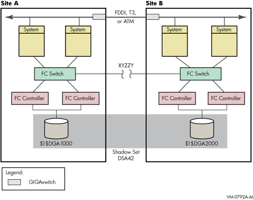
Figure 4-1 depicts a typical multiple-site cluster using Fibre Channel. The figure illustrates the steps required to recover one site manually when the site-to-site storage interconnect fails. These steps must be taken for multiple-site OpenVMS Cluster systems that are running:
Earlier versions of OpenVMS (prior to OpenVMS Alpha Version 7.3–1) that do not support MSCP failover to a served path.
Versions of OpenVMS Alpha that support MSCP failover to a served path (Version 7.3–1 and higher) but serve only a subset of their disks.
If you have chosen to serve only a subset of the disks in your configuration, you must use this configuration method for site recovery for the disks that are not served. One reason to serve only a subset of your disks is that failover of the served disks, from a Fibre Channel interconnect to the LAN interconnects and the inter-site link, can put a very heavy load on these interconnects, which can seriously degrade performance.
To prevent the shadowing driver from automatically recovering shadow sets from connection-related failures, you must perform the following three configuration tasks prior to any failure:
Every device that is a member of a multiple-site shadow set must have its MEMBER_TIMEOUT setting raised to a high value, using the following command:

$ SET SHADOW /MEMBER_TIMEOUT=x ddcu:

This command overrides the SHADOW_MBR_TMO value, which is normally used for a shadow set member. A value for x of 259200 would be a 72-hour wait time.
Every shadow set that spans multiple sites must have its mount verification timeout setting raised to a very high value, higher than the MEMBER_TIMEOUT settings for each member of the shadow set.
Use the following command to increase the mount verification timeout setting for the shadow set:

$ SET SHADOW /MVTIMEOUT=y DSAn

The y value of this command must always be greater than the x value of the SET SHADOW /MEMBER_TIMEOUT= x ddcu: command.
The SET SHADOW /MVTIMEOUT = y command overrides the MVTIMEOUT value, which is normally used for the shadow set. A value for y of 262800 would be a 73-hour wait.
Every shadow set and every shadow set member must have a site qualifier. As already noted, a site qualifier ensures that the read cost is correctly set. The other critical factor is three-member shadow sets. When they are being used, the site qualifier ensures that the master member of the shadow set is properly maintained.
Figure 4-1 shows a shadow set DSA42, whose members are devices $1$DGA1000 and $1$DGA2000. Systems at Site A or Site B have direct access to all devices at both sites via Fibre Channel connections. XYZZY is a theoretical point between the two sites. If the Fibre Channel connection were to break at this point, each site could access different “local” members of DSA42 without error.
For the purpose of this example, Site A is the sole site chosen to retain access to the shadow set.
The following steps must be taken to recover the shadow set at Site A.
On Site A, issue the following command:

$ DISMOUNT /FORCE_REMOVAL=$1$DGA2000:

Once the command has completed, the shadow set is available for use only at site A.
On Site B, issue the following command:

$ SET SHADOW /ABORT_VIRTUAL_UNIT DSA42:

Once the command has completed, the shadow set status is MntVerifyTimeout.
Next, issue the following command to free up the shadow set:

$ DISMOUNT/ABORT DSA42:

These steps must be taken for all affected multiple-site shadow sets.
