Refer to the following guides for more details:
The DIGITAL TCP/IP Services for OpenVMS software includes the PATHWORKS Internet Protocol (PWIP) driver and the PATHWORKS network ancillary control process (ACP) to provide TCP/IP options to PATHWORKS users.
An internet is a set of connected networks that act as a coordinated whole, providing interconnections while allowing individual groups to select the network hardware best suited to their needs. This chapter discusses the following networking and TCP/IP concepts:
It is important to remember that the Internet is not a new kind of physical network. It is a method of interconnecting physical networks and includes a set of conventions for using these networks that allow the computers they reach to interact. While network hardware plays only a minor role in the overall design, understanding the internet technology requires you to distinguish between the low-level mechanisms provided by the hardware and the higher-level facilities provided by the DIGITAL TCP/IP Services for OpenVMS (UCX) software.
A network consists of two or more computer systems linked by communications hardware and software. An open network is a network of open systems. An open system is a computer system with communications software that implements formal, international networking standards (for example, the TCP/IP suite of protocols).
A TCP/IP network supports remote system communication, resource
sharing, and distributed processing. Network users can access resources
on any system in the network and the resources of other vendors'
systems.
2.1.1 Local Area Networks
A local area network (LAN) consists of two or more hosts, all connected
to one broadcast medium by a high-speed communication medium over short
distances. Host computers connect to the communication medium by a
hardware interface that often connects to one of the following LANs:
Ethernet, FDDI, or Token Ring.
2.1.2 Wide Area Networks
A wide area network (WAN) consists of two or more hosts residing in different locations. Communication transmissions are primarily carried for long distances over telephone lines or a similar medium. Each host connects to the communication medium by a hardware interface connected to the WAN. DIGITAL TCP/IP Services for OpenVMS supports the Serial Line Internet Protocol (SLIP) and the Point-to-Point Protocol (PPP) standards.
SLIP is framing protocol that sends IP packets over dialup phone lines. SLIP treats each serial link as a separate connection.
PPP is also a framing protocol that sends IP packets over dialup phone
lines. Like SLIP, PPP also treats each serial link as a separate
network. However, PPP's advantage over SLIP is that it can assign a
temporary network number that applies during the time the connection is
established. This approach allows internet service providers to make
access available to more users because these users only occupy the
line, and therefore the network number, during the connection.
2.1.3 Subnets
You can divide a network into subnetworks. A subnet is a single network within a group of interconnected networks. Subnets are useful for organizing hosts within a network into logical groups. When you use subnet routing, multiple physical networks can share a single network address. You can use local gateways and subnet addresses for each local physical network and cause the network to appear as one single network to other systems.
For example, your company may have only one assigned network number,
even though several physical networks exist. In this scenario, you can
use local gateways and assign a subnet address to each physical network
to make it appear to outside systems that your company has only one
network.
2.2 Internets
An internet is a unified, cooperative collection of two or more networks that support a single, universal communication service. The networks are connected by a host that acts as a gateway. A gateway transfers data from one host to another host on a different network. Underlying communication mechanisms reside on each network. Between these mechanisms and application programs, low-level protocols are hidden to make the collection of networks appear to be a single large network. These interconnected systems agree to conventions, such as procedures for moving data, that enable each computer to communicate with every other computer on the Internet, whether it is locally or remotely connected.
The Internet is a global internet that uses TCP/IP protocols. This
entity is accessible to many universities, military installations,
government research labs, private companies, and individuals.
2.3 Client/Server Model
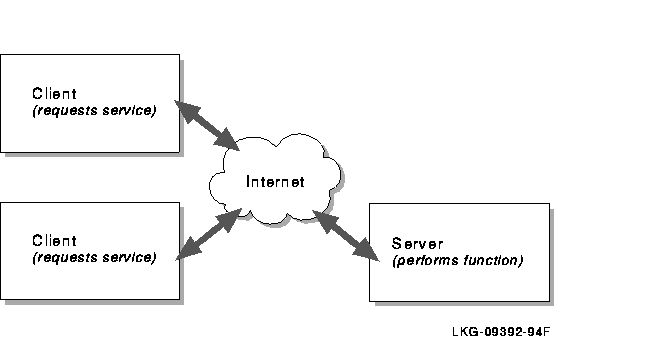
Host-to-host communication takes place between two processes. A process is a program that executes on a host. Any process that offers a service to another process over the network is known as a server. Any process that requests a service from another process over the network is known as a client. Clients request a service from the server and wait for the result. The server performs that service as if it were local to the client. Servers are shared processes that support multiple clients.
Figure 2-1 shows a typical client/server relationship.
Figure 2-1 Client/Server Relationship
Each host in an internet must have a unique Internet Protocol (IP) address. To communicate with a remote host, a local user must know the IP address of the remote host and both hosts must reside on the same internet.
The IP address consists of 32 bits (equivalent to 4 bytes or octets) of information. The 4 bytes are usually expressed in dotted decimal format with each byte a number between 0 and 255. For example, 98.0.2.65 is a valid IP address.
The 4-byte IP address is divided into two parts: the network address and the host number. Within the same network, the IP address of each host has the same network address number but a unique host number. For example, 201.233.20.125 and 201.233.20.130 are two separate hosts on the same network (201.233.20 is the network address and 125 and 130 the host numbers of the two hosts).
Currently, IP addresses are organized into three classes, depending on the size of the network they represent: Class A, Class B, and Class C. Class A networks are extremely large; each Class A network can consist of more than 16 million hosts. Class B networks are smaller with a maximum of 65,534 hosts, and Class C networks must contain fewer than 245 hosts. (These numbers are theoretical. In practice, Class A and Class B networks are usually divided into subnets, which significantly reduces the number of hosts they contain.)
Given that each IP address is 4 bytes, you can tell the relative size of a network based on its IP address, as follows:
See Table 2-1 for examples of the network address for the three classes of networks.
| Class | First Byte | Second Byte | Third Byte | Fourth Byte | Example |
|---|---|---|---|---|---|
| A | 1--126 | x¹ | x¹ | x¹ | 103. x.x.x¹ |
| B | 128--191 | 1--255 | x¹ | x¹ | 153.200. x.x¹ |
| C | 192--223 | 0--255 | 1--254 | x¹ | 203.120.2. x¹ |
The InterNIC is the central organization that assigns these network
addresses to other organizations, which in turn assign the host numbers
represented by x in Table 2-1. Each organization is
responsible for making sure that all attached hosts are properly
numbered. Currently, only Class C networks are available. See Appendix
A for more information about the InterNIC and how to obtain IP
addresses.
2.4.1 Example of IP Addresses
Figure 2-2 shows an example of assigned IP addresses and names for an internet.
Figure 2-2 IP Addresses and Names of a Sample Internet
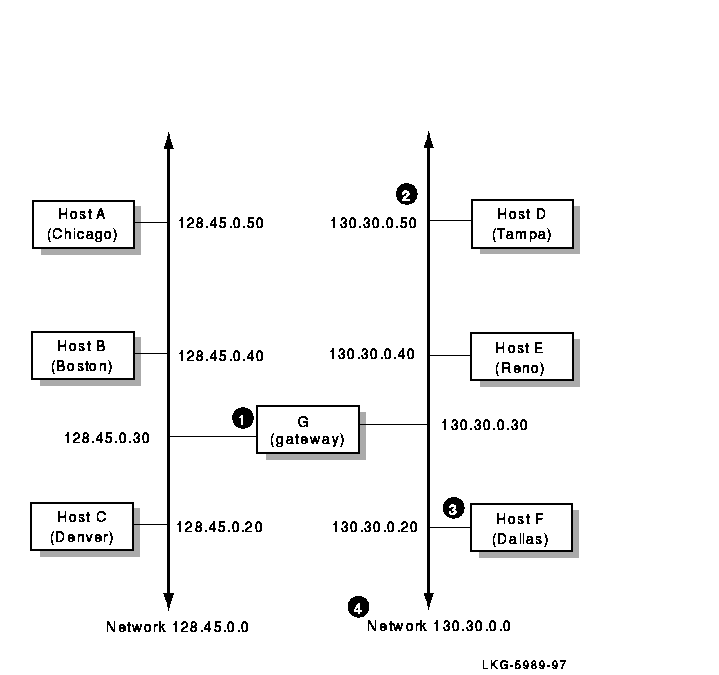
Although the name and address of a host can change, they usually remain
stable for extended time periods.
2.4.2 Network Byte Order
Internet packets carry binary numbers that specify information such as destination addresses and packet lengths, which must be understood by both the sending and receiving hosts. Different machines, however, store 32-bit integers in different ways. The two most common ways are called Little Endian and Big Endian. With Little Endian style, the lowest memory address contains the low-order byte of the integer whereas with Big Endian, it contains the high-order byte of the integer. Thus, direct copying of bytes from one machine to another may change the value of the number.
To solve this problem, the Internet community has defined the Big Endian style as the network standard byte order that all machines must use for binary fields in internet packets. Each host converts binary items from the local representation to network standard byte order before it sends a packet and converts the packet back to the local representation when a packet is received.
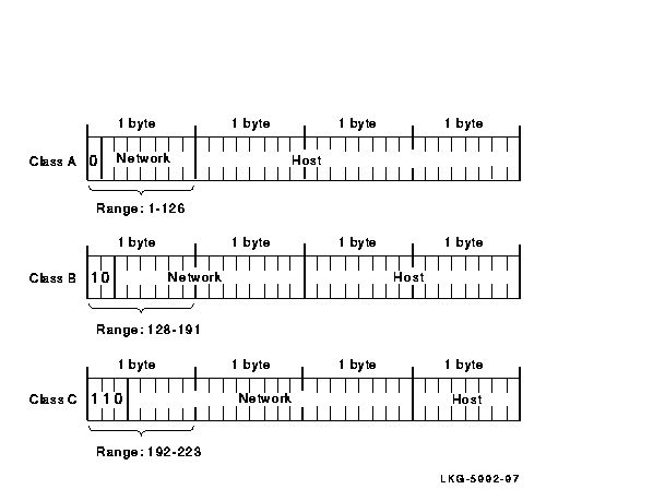
In the network standard byte order, the high-order bits in the network number designate the network class of the IP address. For a Class A network, the first high-order bit is 0. For a Class B network, the first two high-order bits are 10. For a Class C network, the first three high-order bits are 110.
Figure 2-3 shows the bit positions of the IP address for the three network classes.
Figure 2-3 IP Network Classes
Subnet routing requires a different interpretation of IP addresses. A certain number of bits are taken from the octets in the host part of the address and used to specify subnet information.
When using subnet addresses, you use a network mask. The network mask informs the system which bits of the IP address to interpret as the network, subnet, and host addresses. A network mask is a 32-bit number. There is a one-to-one correspondence between the 32 bits in the network mask and the 32 bits in the IP address (the terms network mask and subnet mask can be used interchangeably).
For each bit in the network mask that is turned on (binary 1), the corresponding bit position in the IP address is interpreted as part of the network and subnet address.
The decimal number 255 is 11111111 in binary notation. The value 255 means that an entire 8-bit field is turned on because each bit position is a 1. Generally, the entire 8-bit field is turned either on (255) or off (0). Values other than 255 or 0 can be used. However, by using 255 or 0, you make it easier for users to differentiate between the network, host, and subnet fields.
If the network mask bit position is part of the host field and is turned on, the corresponding bit in the IP address is interpreted as part of the subnet address. If the network mask bit position is part of the host field and is turned off, the corresponding bit in the IP address is interpreted as part of the host address.
All bits in the first (leftmost) byte of the network mask must be turned on (decimal value of 255, binary value of 11111111), because the first byte of the IP address must always be interpreted as the network address regardless of whether there are subnets. If a bit in the first byte of the network mask is turned off, part of the network field of the IP address is interpreted as part of the host address. This may cause errors.
The second and third bytes of the new mask are usually either 255 or 0, depending on how the IP address is to be interpreted. The fourth byte is usually 0, to indicate that the fourth byte of the IP address is part of the host address.
Figures 2_4 and 2-5 illustrate the way different network masks affect the subnet address. As illustrated in Figure 2-4, a Class A network mask can be 255.255.0.0. When the network mask is 255.255.0.0, the first byte is the network address, the second byte is the subnet address, and the third and fourth bytes are the host address.
Figure 2-4 Class A Network Mask, Example 1
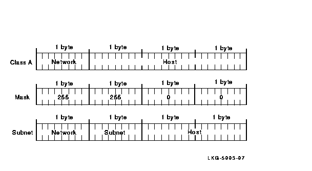
Figure 2-5 shows a Class A network with a network mask of 255.255.255.0. If the network mask is 255.255.255.0, the first byte is the network address, the second and third bytes are the subnet address, and the fourth byte is the host address.
Figure 2-5 Class A Network Mask, Example 2

If a Class B network uses 255.255.255.0 (as shown in Figure 2-6) for a network mask, the first and second bytes are the network address, the third byte is the subnet address, and the fourth byte is the host address.
Figure 2-6 Class B Network Mask
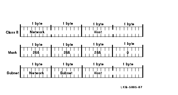
Normally, Class C networks do not have subnets, because only 8 bits are allocated for the host part of the IP address. Eight bits may not be enough to divide between a subnet address and a host address.
The default network masks for each class are as follows:
The broadcast mask interprets the IP address as a broadcast address. The broadcast address allows messages to be sent to all the hosts on the network at the same time. If you use subnets, all the hosts on the same subnet must have the same IP broadcast address.
The default format of the broadcast address consists of the network number followed by all 1s. However, for compatibility it may be necessary to change the IP broadcast address to the network number followed by all 0s, because some operating systems (UNIX BSD 4.2 and DIGITAL UNIX prior to Version 1.2) require all 0s for a broadcast address.
The network number includes the subnet, if there is one.
Note
Problems can occur when systems using all 0s coexist on the same network as systems using all 1s. The two hosts may not be able to interpret each other's broadcast address.
If you know the IP address and the network mask for a particular host,
you can determine the broadcast address by using the following formula:
(NOT networkmask) OR (internetaddress)
For example, if a host has an IP address of 128.50.100.100 and its network mask is 255.255.0.0 (the default), its broadcast mask is 128.50.255.255. The NOT of its network mask is 0.0.255.255. You then substitute the first two fields of the IP address for the two 0s to get the broadcast address.
Table 2-2 lists examples of broadcast addresses.
| Host IP Address | Host Number | Network Class | Network Number | Network Mask | Broadcast Address |
|---|---|---|---|---|---|
| 3.0.0.10 | 10 | A | 3. | 255.0.0.0 | 3.255.255.255 or 3.0.0.0 |
| 11.1.0.12¹ | 12 | A | 11.1. | 255.255.0.0 | 11.1.255.255 or 11.1.0.0 |
| 129.39.0.15 | 15 | B | 129.39. | 255.255.0.0 | 129.39.255.255 or 129.39.0.0 |
| 128.45.2.8¹ | 2.8 | B | 128.45. | 255.255.255.0 | 128.45.2.255 or 128.45.2.0 |
| 192.0.1.8 | 8 | C | 192.0.1. | 255.255.255.0 | 192.0.1.255 or 192.0.1.0 |
| 192.0.1.223 | 223 | C | 192.0.1. | 255.255.255.0 | 192.0.1.255 or 192.0.1.0 |
Routing is the process of moving information, in the form of datagrams, from one host to another over the network. A host has a name that is recognizable to users, such as HARRY or ULTRA. The host name is associated with one or more IP addresses.
The Internet layer deals primarily with addresses. Higher layer protocols (for example, protocols in the Application layer) map the names to addresses. The Internet layer maps the IP addresses to the local network addresses. The local gateway maps a destination not on the local network to the remote network. Figure 2-7 shows internet routing.
Figure 2-7 Internet Routing
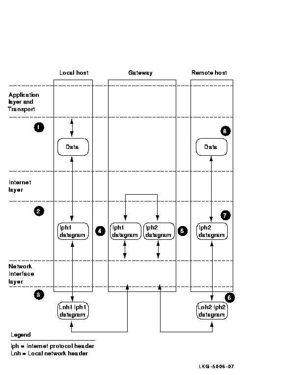
Internet routing follows this progression:
Using subnets allows you to organize hosts within a network into logical groups. A network can be made up of several subnets. A host on a network can access a host on a subnet if there is a gateway connecting the networks, as illustrated in Figure 2-8. The data from the host on the other network routes through the gateway to the network and onto the appropriate subnet, where the destination host receives the data.
See Figure 2-8 for an example of subnet routing on multiple physical networks.
Figure 2-8 Subnet Routing on Multiple Physical Networks
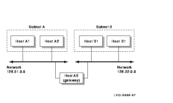
UCX supports dynamic routing. With dynamic routing, your system updates its routing database with routing information supplied over the network by gateways.
The dynamic routing server listens on a User Datagram Protocol (UDP) socket for packets with routing information. If the host is a gateway (internet router), it periodically supplies copies of its routing tables to directly connected hosts or networks.
When the dynamic routing server is started, it reads the UCX$ROUTE.DAT file to create entries in the internet routing table for gateways that were defined by the system manager. Then, it finds all active Internet interfaces (except those marked in loopback). If multiple interfaces are present, the dynamic router assumes that the host forwards packets between networks. The dynamic routing server then transmits a Routing Information Protocol (RIP) request packet on each interface. If the interface supports broadcast packets, the dynamic router sends a broadcast packet. Otherwise, the dynamic router sends a normal packet and listens for RIP request and RIP response packets from other hosts.
When a RIP request packet is received, the dynamic router formulates a reply based on the information maintained in its internal tables. The RIP response packet generated by the server contains a list of known routes, each marked with a hop count metric. The hop count is the number of hops between two hosts, based on the number of different routers needed to traverse the distance between the two hosts. A hop count of 16 or greater is considered infinite.
If one or more of the following conditions exist, the RIP response packets received by the dynamic router are used to update the internet routing tables:
When an update is applied, the dynamic router records the change in its internal tables and generates a RIP response packet to all hosts and networks to which it is directly connected. The dynamic router waits a short period of time (no more than 30 seconds) before modifying the internet routing tables to allow possible unstable situations to be resolved.
In addition to processing incoming packets, the dynamic routing server periodically checks the internet routing table entries. If an entry has not been updated for 3 minutes, the entry's metric is set to infinity and marked for deletion. Deletions are delayed an additional 60 seconds to ensure that the invalidation is propagated throughout the internet.
Hosts that act as gateways supply their routing tables to all directly connected hosts and networks every 30 seconds. The RIP response is sent to either the broadcast destination, an address on a point-to-point link, or the gateway's address on other networks. The normal routing tables are bypassed when sending RIP response packets.