 |
VMS DECwindows Guide to Xlib (Release 4)
Programming: MIT C Binding
6.6.2 Copying Areas of Windows and Pixmaps
Xlib includes the COPY AREA and COPY PLANE routines to enable clients
to copy a rectangular area defined on one window or pixmap (the source)
to an area of another window or pixmap (the destination). COPY AREA
copies areas between drawables of the same root and depth. COPY PLANE
copies a single bit plane of the specified drawable to another
drawable, regardless of their depths. The bit plane is treated as a
stipple with a fill style of FillOpaqueStippled. Both
drawables must have the same root window.
The server refers to the following members of the GC data structure
when copying areas and planes:
|
Function
|
Plane mask
|
|
Clip x origin
|
Clip y origin
|
|
Subwindow mode
|
Clip mask
|
|
Graphics exposures
|
|
If the client calls the COPY PLANE routine, the server additionally
refers to the foreground and background members.
6.7 Defining Regions
A region is an arbitrarily defined area within which
graphics drawing is clipped. In other words, clipping regions are
portions of either windows or pixmaps in which clients can restrict
output. As Chapter 4 notes, the SET CLIP MASK, SET CLIP ORIGIN, and
SET CLIP RECTANGLES routines define clipping regions. Xlib provides
other, more convenient, routines that enable clients to define regions
and associate them with drawables without having to change graphics
context values directly.
This section describes how to create and manage clipping using Xlib
region routines.
6.7.1 Creating Regions
Xlib includes the CREATE REGION and POLYGON REGION routines for
creating regions. CREATE REGION creates an empty region. POLYGON REGION
creates a region defined by an array of points.
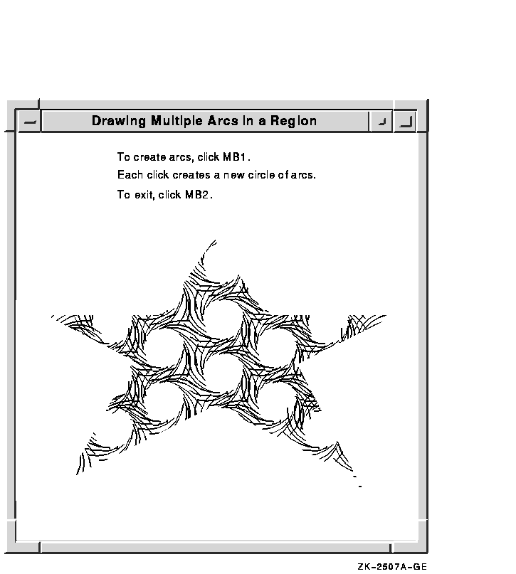
Example 6-7 illustrates using POLYGON REGION to create a star-shaped
region. Using the DRAW ARCS routine of Example 6-4, the program
limits arc drawing to the star region.
| Example 6-7 Defining a Region Using the
POLYGON REGION Routine |
                    .
                    .
                    .
/***** Create the graphics context *****/
static void doCreateGraphicsContext( )
{
    XPoint pt_arr[NUM_PTS];
    XGCValues xgcv;

(1)  pt_arr[0].x = 75;
    pt_arr[0].y = 500;
    pt_arr[1].x = 300;
    pt_arr[1].y = 100;
    pt_arr[2].x = 525;
    pt_arr[2].y = 500;
    pt_arr[3].x = 50;
    pt_arr[3].y = 225;
    pt_arr[4].x = 575;
    pt_arr[4].y = 225;
    pt_arr[5].x = 75;
    pt_arr[5].y = 500;

    /* Create graphics context. */

    xgcv.foreground = doDefineColor(2);
    xgcv.background = doDefineColor(3);

    gc = XCreateGC(dpy, win, GCForeground | GCBackground, &xgcv);
(2)  star_region = XPolygonRegion(&pt_arr, NUM_PTS, WindingRule);
}
                    .
                    .
                    .
/***** Handle events *****/
static void doHandleEvents( )
{
    XEvent event;

    for ( ; ; ) {
        XNextEvent(dpy, &event);
        switch (event.type) {
            case Expose:                doExpose(&event); break;
            case ButtonPress:           doButtonPress(&event); break;
        }
    }
}


/***** Write a message *****/
static void doExpose(eventP)
XEvent *eventP;
{
    char message1[ ] = {"To create arcs in a region, click MB1"};
    char message2[ ] = {"Each click creates a new circle of arcs."};
    char message3[ ] = {"To exit, click MB2"};

    XDrawImageString(dpy, win, gc, 150, 25, message1, strlen(message1));
    XDrawImageString(dpy, win, gc, 150, 50, message2, strlen(message2));
    XDrawImageString(dpy, win, gc, 150, 75, message3, strlen(message3));
}


/***** Draw the arcs *****/
static void doButtonPress(eventP)
XEvent *eventP;
{
#define ARC_CNT 16
#define RADIUS 50
#define INNER_RADIUS  20
    XArc arc_arr[ARC_CNT];
    int i;
    int x = eventP->xbutton.x;
    int y = eventP->xbutton.y;

    if (eventP->xbutton.button == Button2) sys$exit (1);

(3)  XSetRegion(dpy, gc, star_region);
    for (i=0;i<ARC_CNT;i++) {
        arc_arr[i].angle1 = (64*360)/ARC_CNT * i;
        arc_arr[i].angle2 = (64*360)/ARC_CNT*3;
        arc_arr[i].width = RADIUS*2;
        arc_arr[i].height = RADIUS*2;
        arc_arr[i].x = x - RADIUS + sin(2*3.14159/ARC_CNT*i) * INNER_RADIUS;
        arc_arr[i].y = y - RADIUS + cos(2*3.14159/ARC_CNT*i) * INNER_RADIUS;
    }

    XDrawArcs(dpy, win, gc, &arc_arr, ARC_CNT);
}
|
- Define an array of point data structures to
define the clipping region.
- Define the clipping region. Note that
defining the region does not associate it with a graphics context.
Fill rule can be either even/odd rule or winding rule. For more
information about fill rule, see Chapter 4.
- Associate the region with a graphics
context. The association sets fields in the specified GC data structure
that control clipping. Drawables that refer to the GC data structure
have output clipped to the region.
Figure 6-8 illustrates sample output from the program.
Figure 6-8 Arcs Drawn Within a Region

6.7.2 Managing Regions
Xlib includes routines that enable clients to do the following:
- Move and shrink a region
- Compute the intersection, union, and results of two regions
- Determine if regions are empty or equal
- Locate a point or rectangle within a region
Table 6-5 lists and describes Xlib routines that manage regions.
Table 6-5 Routines for Managing Regions
| Routine |
Description |
| Creating, Copying, and Destroying |
|
CREATE REGION
|
Creates a new empty region
|
|
SET REGION
|
Sets the clip mask of a GC to a region
|
|
DESTROY REGION
|
Deallocates storage associated with a specified region
|
| Moving and Shrinking |
|
OFFSET REGION
|
Moves a region a specified amount
|
|
SHRINK REGION
|
Reduces a region a specified amount
|
| Computing |
|
INTERSECT REGION
|
Computes the intersection of two regions
|
|
UNION REGION
|
Computes the union of two regions
|
|
UNION RECT WITH REGION
|
Creates a union of a source region with a rectangle
|
|
SUBTRACT REGION
|
Subtracts two regions
|
|
XOR REGION
|
Calculates the difference between the union and intersection of two
regions
|
| Determining If Regions Are Empty or Equal |
|
EMPTY REGION
|
Determines if a region is empty
|
|
EQUAL REGION
|
Determines if two regions have the same offset, size, and shape
|
| Locating a Point or Rectangle Within a Region |
|
POINT IN REGION
|
Determines if a point is within a region
|
|
RECT IN REGION
|
Determines if a rectangle is within a region
|
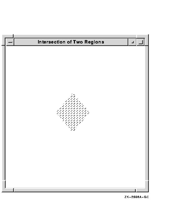
Example 6-8 illustrates creating a region from the intersection of
two others.
| Example 6-8 Defining the Intersection of Two
Regions |
Pixmap pixmap1, pixmap2, pixmap3;
Region region1, region2, region3;
                    .
                    .
                    .

/***** doInitialize *****/
static void doInitialize( )
{
    dpy = XOpenDisplay(0);

    screen = XDefaultScreenOfDisplay(dpy);

    doCreateWindows( );

    doCreateGraphicsContext( );

    doCreatePixmap( );

    doCreateRegion( );

    doMapWindows( );
}
                    .
                    .
                    .
/***** Create the pixmap *****/

(1)static void doCreatePixmap( )
{
    pixmap1 = XCreatePixmap(dpy, win, pixWidth, pixHeight,
              DefaultDepthOfScreen(screen));
    pixmap2 = XCreatePixmap(dpy, win, pixWidth, pixHeight,
              DefaultDepthOfScreen(screen));
    pixmap3 = XCreatePixmap(dpy, win, pixWidth, pixHeight,
              DefaultDepthOfScreen(screen));

    /* Set the pixmap background */
    XFillRectangle(dpy, pixmap1, gc, 0, 0, pixWidth, pixHeight);
    XFillRectangle(dpy, pixmap2, gc, 0, 0, pixWidth, pixHeight);
    XFillRectangle(dpy, pixmap3, gc, 0, 0, pixWidth, pixHeight);

    /* Redefine foreground value for line drawing and text */
    XSetForeground(dpy, gc, doDefineColor(2));

    /* Draw Line into the pixmap */
    XDrawLine(dpy, pixmap1, gc, 0, 4, 0, 8);
    XDrawLine(dpy, pixmap2, gc, 4, 0, 8, 0);
    XDrawLine(dpy, pixmap3, gc, 0, 4, 0, 8);
    XDrawLine(dpy, pixmap3, gc, 4, 0, 8, 0);

}
/***** Create the region *****/
static void doCreateRegion( )
{
(2)  XPoint pt_arr_1[num_pts], pt_arr_2[num_pts];

    pt_arr_1[0].x = 200;
    pt_arr_1[0].y = 100;
    pt_arr_1[1].x = 50;
    pt_arr_1[1].y = 300;
    pt_arr_1[2].x = 200;
    pt_arr_1[2].y = 500;
    pt_arr_1[3].x = 350;
    pt_arr_1[3].y = 300;

    pt_arr_2[0].x = 400;
    pt_arr_2[0].y = 100;
    pt_arr_2[1].x = 250;
    pt_arr_2[1].y = 300;
    pt_arr_2[2].x = 400;
    pt_arr_2[2].y = 500;
    pt_arr_2[3].x = 550;
    pt_arr_2[3].y = 300;

    region1 = XPolygonRegion(pt_arr_1, num_pts, WindingRule);
    region2 = XPolygonRegion(pt_arr_2, num_pts, WindingRule);

}
                    .
                    .
                    .
/***** Handle events *****/
static void doHandleEvents( )
{
    XEvent event;

    for ( ; ; ) {
        XNextEvent(dpy, &event);
        switch (event.type) {
            case Expose:                doExpose(&event); break;
            case ButtonPress:           i++; doButtonPress(&event); break;
        }
    }
}

/***** Write a message *****/
static void doExpose(eventP)
XEvent *eventP;
{
    char message1[ ] = {"To map regions click MB1 three times."};
    char message2[ ] = {"To exit, click MB2."};

    XDrawImageString(dpy, win, gc, 150, 25, message1, strlen(message1));
    XDrawImageString(dpy, win, gc, 150, 50, message2, strlen(message2));
}
/***** Map the regions when the button is pressed *****/
static void doButtonPress(eventP)
XEvent *eventP;
{
    char message3[ ] = {"That's it! Click MB2 to exit."};

    if (eventP->xbutton.button == Button2) sys$exit (1);
    if (i == 1){

       /* Redefine the fill style for stippling */
(3)          XSetFillStyle(dpy, gc, FillTiled);

        XClearWindow(dpy, win);
        XSetTile(dpy, gc, pixmap1);
(4)      XSetRegion(dpy, gc, region1);
(5)      XFillRectangle(dpy, win, gc, xOrigin, yOrigin, winW, winH);
        }
    else if (i == 2){
(6)      XClearWindow(dpy, win);
        XSetTile(dpy, gc, pixmap2);
        XSetRegion(dpy, gc, region2);
        XFillRectangle(dpy, win, gc, xOrigin, yOrigin, winW, winH);
        }
    else if (i == 3){
        XClearWindow(dpy, win);
(7)      region3 = XCreateRegion();
        XIntersectRegion(region1, region2, region3);
        XSetTile(dpy, gc, pixmap3);
        XSetRegion(dpy, gc, region3);
        XFillRectangle(dpy, win, gc, xOrigin, yOrigin, winW, winH);
        }
    else{
        /* To draw text, redefine the fill style as solid */
(8)      XSetFillStyle(dpy, gc, FillSolid);
        XDrawImageString(dpy, win, gc, 150, 50, message3, strlen(message3));
        }
}
|
- Pixmaps are used to tile the window with
horizontal, vertical, and cross-hatched lines. For information about
pixmaps, see Chapter 7.
- Arrays of point data structures define two
regions.
- After writing messages in the window, the
fill style defined in the GC data structure is changed to tile the
window with pixmaps. The subsequent call to SET TILE defines one of the
three pixmaps created earlier as the window background pixmap. For
information about fill styles and tiling, see Chapter 4.
- The SET REGION routine specifies the clipping
region in the graphics context. The region defined by pt_arr1
is first specified.
- FILL RECTANGLE repaints the window, filling
it with the tiling pattern defined in pixmap1. Tiling is
restricted to the region defined by region1.
- Before specifying a new tiling pattern and
region, the window is cleared.
- CREATE REGION creates an empty region and
returns an identifier, region3. Xlib returns the results of
intersecting region1 and region2 to region3.
- Before displaying a final message in the
window, the fill style is redefined to solid to enable text writing.
Figure 6-9 illustrates the output from the program.
Figure 6-9 Intersection of Two Regions

6.8 Defining Cursors
A cursor is a bit image on the screen that indicates
either the movement of a pointing device or the place where text will
next appear.
Xlib enables clients to associate a cursor with each window they
create. After making the association between cursor and window, the
cursor is visible whenever it is in the window. If the cursor indicates
movement of a pointing device, the movement of the cursor in the window
automatically reflects the movement of the device.
Xlib and VMS DECwindows provide fonts of predefined cursors. Clients
that want to create their own cursors can either define a font of
shapes and masks or create cursors using pixmaps.
This section describes the following:
- Creating cursors using the Xlib cursor font, a font of shapes and
masks, and pixmaps
- Associating cursors with windows
- Managing cursors
- Freeing memory allocated to cursors when clients no longer need them
6.8.1 Creating Cursors
Xlib enables clients to use predefined cursors or to create their own
cursors.
To create a predefined Xlib cursor, use the CREATE FONT CURSOR routine.
Xlib cursors are predefined in DECW$INCLUDE:CURSORFONT.H. See the
X and Motif Quick Reference Guide for a list of the constants that refer to the predefined
Xlib cursors.
The following example creates a sailboat cursor, one of the predefined
Xlib cursors, and associates the cursor with a window:
Cursor fontcursor;
                .
                .
                .

fontcursor = XCreateFontCursor(dpy, XC_sailboat);
XDefineCursor(dpy, win, fontcursor);
|
The DEFINE CURSOR routine makes the sailboat cursor automatically
visible when the pointer is in window win.
In addition to the standard Xlib cursors, VMS DECwindows provides
another set of cursors. VMS DECwindows cursors are predefined in
SYS$LIBRARY:DECW$CURSOR.H. Table 6-6 lists the constants that refer
to the predefined VMS DECwindows cursors.
Table 6-6 Predefined VMS DECwindows Cursors
|
decw$c_select_cursor
|
decw$c_leftselect_cursor
|
|
decw$c_help_select_cursor
|
decw$c_wait_cursor
|
|
decw$c_inactive_cursor
|
decw$c_resize_cursor
|
|
decw$c_vpane_cursor
|
decw$c_hpane_cursor
|
|
decw$c_text_insertion_cursor
|
decw$c_text_insertion_bl_cursor
|
|
decw$c_cross_hair_cursor
|
decw$c_draw_cursor
|
|
decw$c_pencil_cursor
|
decw$c_rpencil_cursor
|
|
decw$c_center_cursor
|
decw$c_rightselect_cursor
|
|
decw$c_wselect_cursor
|
decw$c_eselect_cursor
|
|
decw$c_x_cursor
|
decw$c_circle_cursor
|
|
decw$c_mouse_cursor
|
decw$c_lpencil_cursor
|
|
decw$c_leftgrab_cursor
|
decw$c_grabhand_cursor
|
|
decw$c_rightgrab_cursor
|
decw$c_leftpointing_cursor
|
|
decw$c_uppointing_cursor
|
decw$c_rightpointing_cursor
|
To create a predefined VMS DECwindows cursor, use the CREATE GLYPH
CURSOR routine.
CREATE GLYPH CURSOR selects a cursor shape and cursor mask from the VMS
DECwindows cursor font, defines how the cursor appears on the screen,
and assigns a unique cursor identifier. The following example
illustrates creating the select cursor and associating the cursor with
a window:
Font cursorfont
Cursor glyphcursor;
XColor forecolor, backcolor;
                  .
                  .
                  .
cursorfont = XLoadFont(dpy, "decw$cursor");
XSetFont(dpy, gc, cursorfont);

glyphcursor = XCreateGlyphCursor(dpy, cursorfont, cursorfont,
     decw$c_select_cursor, decw$c_select_cursor + 1,
     &forecolor, &backcolor);
XDefineCursor(dpy, win, glyphcursor);
|
To create client-defined cursors, either create a font of cursor shapes
or define cursors using pixmaps. In each case, the cursor consists of
the following components:
- Shape---Defines the cursor as it appears without modification in a
window
- Mask---Acts as a clip mask to define how the cursor actually
appears in a window
- Background color---Specifies RGB values used for the cursor
background
- Foreground color---Specifies RGB values used for the cursor
foreground
- Hotspot---Defines the position on the cursor that reflects
movements of the pointing device
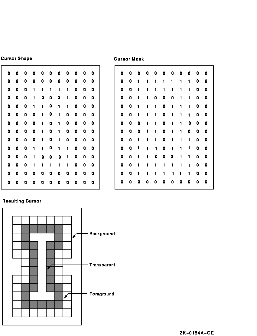
Figure 6-10 illustrates the relationship between the cursor shape and
the cursor mask. The cursor shape defines the cursor as it would appear
on the screen without modification. The cursor mask bits that are set
to 1 select which bits of the cursor shape are actually displayed. If
the mask bit has a value of 1, the corresponding shape bit is displayed
whether it has a value of 1 or 0. If the mask bit has a value of 0, the
corresponding shape bit is not displayed.
In the resulting cursor shape, bits with a 0 value are displayed in the
specified background color; bits with a 1 value are displayed in the
specified foreground color.
Figure 6-10 Cursor Shape and Cursor Mask

To create a client-defined cursor from a font of glyphs, use the CREATE
GLYPH CURSOR routine, specifying the cursor and mask fonts that contain
the glyphs. To create a cursor from pixmaps, use the CREATE PIXMAP
CURSOR routine.
The pixmaps must have a depth of one. If the depth is not one, the
server generates an error.
The size of the pixmap cursor must be supported by the display on which
the cursor is visible. To determine the supported size closest to the
size the client specifies, use the QUERY BEST CURSOR routine.
Example 6-9 illustrates creating a pencil pointer cursor from two
pixmaps.
| Example 6-9 Creating a Pixmap Cursor |
#include <decw$include/Xlib.h>
#include <decw$include/Xutil.h>

#define winW 600
#define winH 600
#define pencil_width 16
#define pencil_height 16
#define pencil_xhot 1
#define pencil_yhot 15

Display *dpy;
Window win;
Pixmap pixmap, pencil;
Pixmap pencil_mask;
Cursor pencil_cursor;
                         .
                         .
                         .
static char pencil_bits[] = {
   0x0000, 0x0070, 0x0000, 0x0088, 0x0000, 0x008C, 0x0000, 0x0096,
   0x0000, 0x0069, 0x0080, 0x0030, 0x0040, 0x0010, 0x0020, 0x0008,
   0x0010, 0x0004, 0x0008, 0x0002, 0x0008, 0x0001, 0x0094, 0x0000,
   0x0064, 0x0000, 0x001E, 0x0000, 0x0006, 0x0000, 0x0000, 0x0000};

static char pencil_mask_bits[] = {
   0x00, 0xF8, 0x00, 0xFC, 0x00, 0xFE, 0x00, 0xFF, 0x80, 0xFF, 0xC0, 0x7F,
   0xE0, 0x3F, 0xF0, 0x1F, 0xF8, 0x0F, 0xFC, 0x07, 0xFC, 0x03, 0xFE, 0x01,
   0xFE, 0x00, 0x7F, 0x00, 0x1F, 0x00, 0x07, 0x00};
                         .
                         .
                         .
/***** Create the cursor *****/
static void doCreateCursor( )
{
    XColor dummy, cursor_foreground, cursor_background;

     /*Create pixmaps for cursor */
(1)  pixmap = XCreatePixmap(dpy, XDefaultRootWindow(dpy), 1, 1, 1);

(2)  XLookupColor(dpy, XDefaultColormapOfScreen(screen), "black",
        &dummy, &cursor_foreground);
    XLookupColor(dpy, XDefaultColormapOfScreen(screen), "white",
        &dummy, &cursor_background);
(3)  pencil = XCreatePixmapFromBitmapData(dpy, pixmap, pencil_bits,
        pencil_width, pencil_height, 1, 0, 1);
    pencil_mask = XCreatePixmapFromBitmapData(dpy, pixmap, pencil_mask_bits,
        pencil_width, pencil_height, 1, 0, 1);

(4)  pencil_cursor = XCreatePixmapCursor(dpy, pencil, pencil_mask,
        &cursor_foreground, &cursor_background, pencil_xhot, pencil_yhot);
    XDefineCursor(dpy, win, pencil_cursor);
}
|
|


