HP OpenVMS Systems Documentation |
Guidelines for OpenVMS Cluster Configurations
7.2.1 Fibre Channel Remedial KitsQualification of new Fibre Channel hardware and larger configurations is ongoing. New hardware and larger configurations may necessitate enhancements to the Fibre Channel support in OpenVMS. Between releases of OpenVMS, enhancements and corrections to Fibre Channel software are made available by means of remedial kits. Compaq recommends that you monitor the Fibre Channel web site ( http://www.openvms.compaq.com/openvms/fibre/ ) and the Compaq support web site ( http://h18000.www1.hp.com/support/ ) for updates for the operating system version you are running.
The latest version of each kit is always posted to the Compaq support
web site.
Shared Fibre Channel OpenVMS Cluster storage is supported in both mixed-version and mixed-architecture OpenVMS Cluster systems. The following configuration requirements must be observed:
7.2.3 Fibre Channel and Volume Shadowing for OpenVMS
Since Fibre Channel support was introduced in OpenVMS Alpha, shadowing
of directly connected Fibre Channel storage using Volume Shadowing for
OpenVMS, has been available. OpenVMS Alpha Version 7.2-1 extended this
support to the shadowing of Fibre Channel multipath devices.
Fibre Channel is supported in all OpenVMS Galaxy configurations. For
more information about Galaxy configurations, see the OpenVMS Alpha Partitioning and Galaxy Guide.
This section presents example Fibre Channel configurations. The
configurations build on each other, starting with the smallest valid
configuration and adding redundant components for increasing levels of
availability, performance, and scalability.
Figure 7-3 shows a single system using Fibre Channel as a storage interconnect. Figure 7-3 Single Host With One Dual-Ported Storage Controller 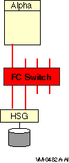
Note the following about this configuration:
7.3.2 Multiple Hosts With One Dual-Ported Storage ControllerFigure 7-4 shows multiple hosts connected to a dual-ported storage subsystem. Figure 7-4 Multiple Hosts With One Dual-Ported Storage Controller 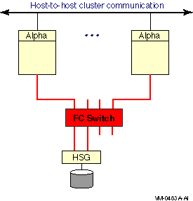
Note the following about this configuration:
Figure 7-5 Multiple Hosts With Storage Controller Redundancy 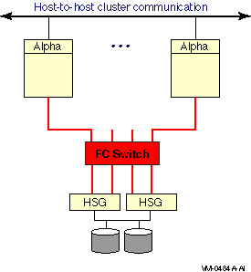
This configuration offers the following advantages:
Figure 7-6 Multiple Hosts With Multiple Independent Switches 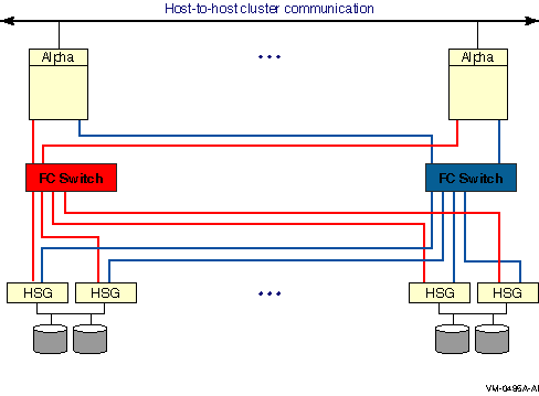
This two-switch configuration offers the advantages of the previous configurations plus the following:
Figure 7-7 Multiple Hosts With Dual Fabrics 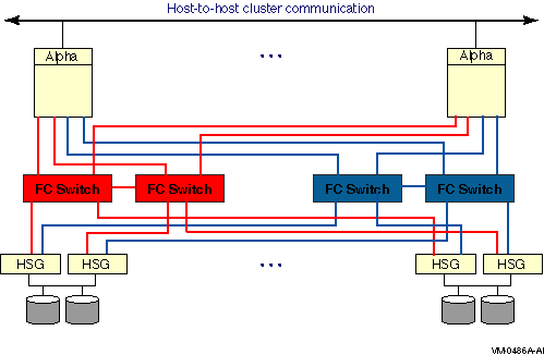
This dual-fabric configuration offers the advantages of the previous configurations plus the following advantages:
Figure 7-8 shows multiple hosts connected to two fabrics. Each fabric has four switches. Figure 7-8 Multiple Hosts With Larger Dual Fabrics 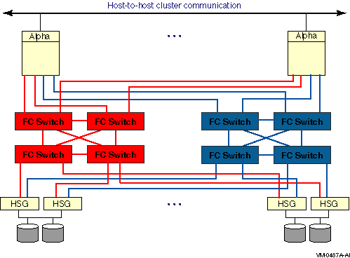
Figure 7-9 shows multiple hosts connected to four fabrics. Each fabric has four switches. Figure 7-9 Multiple Hosts With Four Fabrics 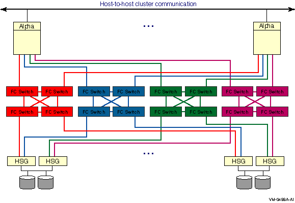
7.4 Fibre Channel Addresses, WWIDs, and Device Names
Fibre Channel devices for disk and tape storage come with
factory-assigned worldwide IDs (WWIDs). These WWIDs are used by the
system for automatic FC address assignment. The FC WWIDs and addresses
also provide the means for the system manager to identify and locate
devices in the FC configuration. The FC WWIDs and adresses are
displayed, for example, by the Alpha console and by the HSG console. It
is necessary, therefore, for the system manager to understand the
meaning of these identifiers and how they relate to OpenVMS device
names.
In most situations, Fibre Channel devices are configured to have temporary addresses. The device's address is assigned automatically each time the interconnect initializes. The device may receive a new address each time a Fibre Channel is reconfigured and reinitialized. This is done so that Fibre Channel devices do not require the use of address jumpers. There is one Fibre Channel address per port, as shown in Figure 7-10. Figure 7-10 Fibre Channel Host and Port Addresses 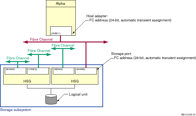
In order to provide more permanent identification, each port on each device has a WWID, which is assigned at the factory. Every Fibre Channel WWID is unique. Fibre Channel also has node WWIDs to identify multiported devices. WWIDs are used by the system to detect and recover from automatic address changes. They are useful to system managers for identifying and locating physical devices. Figure 7-11 shows Fibre Channel components with their factory-assigned WWIDs and their Fibre Channel addresses. Figure 7-11 Fibre Channel Host and Port WWIDs and Addresses 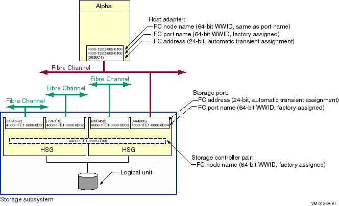
Note the following about this figure:
7.4.2 OpenVMS Names for Fibre Channel Devices
There is an OpenVMS name for each Fibre Channel storage adapter, for
each path from the storage adapter to the storage subsystem, and for
each storage device. These sections apply to both disk devices and tape
devices, except for Section 7.4.2.3, which is specific to disk devices.
Tape device names are described in Section 7.5.
Fibre Channel storage adapter names, which are automatically assigned by OpenVMS, take the form FGx0 :
The naming design places a limit of 26 adapters per system. This naming may be modified in future releases to support a larger number of adapters. Fibre Channel adapters can run multiple protocols, such as SCSI and LAN. Each protocol is a pseudodevice associated with the adapter. For the initial implementation, just the SCSI protocol is supported. The SCSI pseudodevice name is PGx0 , where x represents the same unit letter as the associated FGx0 adapter. These names are illustrated in Figure 7-12. Figure 7-12 Fibre Channel Initiator and Target Names 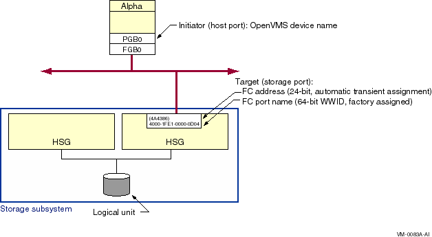
7.4.2.2 Fibre Channel Path NamesWith the introduction of multipath SCSI support, as described in Chapter 6, it is necessary to identify specific paths from the host to the storage subsystem. This is done by concatenating the SCSI pseudodevice name, a decimal point (.), and the WWID of the storage subsystem port that is being accessed. For example, the Fibre Channel path shown in Figure 7-12 is named PGB0.4000-1FE1-0000-0D04.
Refer to Chapter 6 for more information on the display and use of
the Fibre Channel path name.
The four identifiers associated with each FC disk device are shown in Figure 7-13. Figure 7-13 Fibre Channel Disk Device Naming 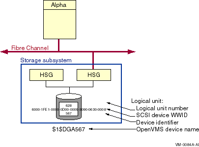
The logical unit number (LUN) is used by the system as the address of a specific device within the storage subsystem. This number is set and displayed from the HSG console by the system manager. It can also be displayed by the OpenVMS SDA utility. Each Fibre Channel disk device also has a WWID to provide permanent, unique identification of the device. The HSG device WWID is 128 bits. Half of this identifier is the WWID of the HSG that created the logical storage device, and the other half is specific to the logical device. The device WWID is displayed by the HSG console and the AlphaServer console. The third identifier associated with the storage device is a user-assigned device identifier. A device identifier has the following attributes:
The device identifier has a value of 567 in Figure 7-13. This value is used by OpenVMS to form the device name so it must be unique throughout the cluster. (It may be convenient to set the device identifier to the same value as the logical unit number (LUN). This is permitted as long as the device identifier is unique throughout the cluster.)
A Fibre Channel storage device name is formed by the operating system
from the constant
$1$DGA
and a device identifier,
nnnnn
. The only variable part of the name is its device identifier, which
you assign at the HSG console. Figure 7-13 shows a storage device
that is known to the host as
$1$DGA567
.
This section describes the configuration requirements and user commands
necessary to utilize the Fibre Channel tape functionality. Fibre
Channel tape functionality refers to the support of SCSI tapes and SCSI
tape libraries in an OpenVMS Cluster system with shared Fibre Channel
storage. The SCSI tapes and libraries are connected to the Fibre
Channel by a Fibre-to-SCSI bridge known as the Modular Data Router
(MDR).
Following is the minimum Fibre Channel tape hardware configuration:
7.5.2 Overview of Fibre Channel Tape Device NamingThis section provides detailed background information about Fibre Channel Tape device naming.
Tape and medium changer devices are automatically named and configured
using the SYSMAN IO FIND and IO AUTOCONFIGURE commands described in
Section 7.5.3. System managers who configure tapes on Fibre Channel
should refer directly to this section for the tape configuration
procedure.
Fibre Channel tapes and medium changers are named using a scheme similar to Fibre Channel disk naming. On parallel SCSI, the device name of a directly attached tape implies the physical location of the device; for example, MKB301 resides on bus B, SCSI target ID 3, and LUN 1. Such a naming scheme does not scale well for Fibre Channel configurations, in which the number of targets or nodes can be very large. Fibre Channel tape names are in the form $2$MGAn. The letter for the controller is always A, and the prefix is $2$. The device mnemonic is MG for tapes and GG for medium changers. The device unit n is automatically generated by OpenVMS. The name creation algorithm chooses the first free unit number, starting with zero. The first tape discovered on the Fibre Channel is named $2$MGA0, the next is named $2$MGA1, and so forth. Similarly, the first medium changer detected on the Fibre Channel is named $2$GGA0. The naming of tapes and medium changers on parallel SCSI buses remains the same. Note the use of allocation class 2. Allocation class 1 is already used by devices whose name is keyed by a user-defined identifier (UDID), as with HSG Fibre Channel disks ($1$DGAnnnn) and HSG console command LUNs ($1$GGAnnnn). An allocation class of 2 is used by devices whose names are obtained from the file, SYS$DEVICES.DAT. The names are based on a worldwide identifier (WWID) key, as described in the following sections. Also note that, while GG is the same mnemonic used for both medium changers and HSG Command Console LUNs (CCLs), medium changers always have an allocation class of 2 and HSG CCLs an allocation class of 1. Tape and medium changer names are automatically kept consistent within a single OpenVMS Cluster system. Once a tape device is named by any node in the cluster, all other nodes in the cluster automatically choose the same name for that device, even if this overrides the first free unit number algorithm. The chosen device name remains the same through all subsequent reboot operations in the cluster.
If multiple nonclustered Alpha systems exist on a SAN and need to
access the same tape device on the Fibre Channel, then the upper-level
application must provide consistent naming and synchronized access.
For each Fibre Channel tape device name, OpenVMS must uniquely identify the physical device that is associated with that name. In parallel SCSI, directly attached devices are uniquely identified by their physical path (port/target/LUN). Fibre Channel disks are uniquely identified by user-defined identifiers (UDIDs). These strategies are either unscalable or unavailable for Fibre Channel tapes and medium changers. Therefore, the identifier for a given Fibre Channel tape or medium changer device is its worldwide identifier (WWID). The WWID resides in the device firmware and is required to be unique by the Fibre Channel standards. WWIDs can take several forms, for example:
The overall WWID consists of the WWID data prefixed by a binary WWID header, which is a longword describing the length and type of WWID data. In general, if a device reports an IEEE WWID, OpenVMS chooses this as the unique identifying WWID for the device. If the device does not report such a WWID, then the ASCII WWID is used. If the device reports neither an IEEE WWID nor serial number information, then OpenVMS does not configure the device. During the device discovery process, OpenVMS rejects the device with the following message:
The WWID structures can be a mix of binary and ASCII data. These formats are displayable and are intended to be consistent with those defined by the console WWIDMGR utility. Refer to the WWIDMGR User's Manual for additional information. Note that if the data following the WWID header is pure ASCII data, it must be enclosed in double quotation marks. The displayable format of a 64-bit IEEE WWID consists of an 8-digit hexadecimal number in ASCII (the WWID header), followed by a colon (:) and then the IEEE WWID data. For example:
The displayable format of an ASCII WWID consists of an 8-digit WWID header, followed by a colon (:) and then the concatenation of the 8-byte vendor ID plus the 16-byte product ID plus the serial number. For example:
7.5.2.3 File-Based Device NamingFibre Channel tape and medium changer devices are configured according to information found in the SYS$SYSTEM:SYS$DEVICES.DAT file. This is an ASCII file consisting of two consecutive records per device, where the two records are in the following form:
During autoconfiguration, the Fibre Channel is probed and the WWIDs are fetched for all devices. If the fetched WWID matches an entry in the memory-resident copy of the SYS$DEVICES.DAT file, then the device is configured using the device name that has been paired with that WWID.
As an example, the following portion of SYS$DEVICES.DAT causes the eventual configuration of devices named $2$MGA300 and $2$MGA23:
Although the file is typically read and written only by OpenVMS utilities, in rare instances you may need to edit the file. In OpenVMS Alpha Version 7.3, you can change only the unit number of the device, as described in Section 7.5.5. The internal syntax rules governing the file are summarized as follows:
Similarly, on the line containing WWID = , any white space (or none) can appear on either side of the equals sign. All lines must be left-justified, and all lines must be less than 512 characters. The parsing of this file is not case sensitive, with one important exception: all characters enclosed within double quotation marks are taken literally, so that characters such as spaces and lowercase letters are significant. In the case of ASCII data enclosed by double quotation marks, there must be no space between the colon and the double quotation mark. Also, if more than one WWID = line follows a single [Device devnam] line, the last WWID = value takes precedence. Normally, however, there is exactly one WWID = line per [Device devnam] line. Similarly, if two or more [Device devnam] lines specify the same device name but different WWIDs, only the last device name and WWID specified in the file is used. This file is read at boot time, and it is also read from and written to by the SYSMAN IO FIND_WWID command. If there are additional system-specific copies of the SYS$DEVICES.DAT file, their tape naming records become automatically compatible as a result of running SYSMAN IO FIND_WWID on each system. The SYSMAN IO FIND_WWID command is described in more detail in the following section.
|