HP OpenVMS Systems Documentation |
DECnet-Plus for OpenVMS
|
||||||||||||||||||||||||||||||||||||||||||||||||||||
| Previous | Contents | Index |
The DECnet-Plus for OpenVMS Event Dispatcher (EVD) software reports significant events that occur during network operation. An event is an occurrence of a normal or abnormal condition that an entity detects. As directed by you, DECnet-Plus for OpenVMS maintains records of specific or general categories of events. These records can help you track the status of network components.
Many events are informational. They record changes that you or the DECnet-Plus for OpenVMS software makes to components of the local system, or to those remote system entities that the local system's Event Dispatcher is tracking. Other events report potential or current problems in the physical parameters of the network.
You can set up event dispatching on a particular system, between two
systems, or across multiple, distributed systems. The event-dispatching
component can report events that occur on any system that runs
DECnet-Plus software, and it is also capable of logging the events of
remote Phase IV nodes via the DECnet-Plus Event Dispatcher relay.
2.8.7 CMIP Management Listener (CML)
The CMIP Management Listener (CML) is the DECnet-Plus management module that implements DNA Common Management Information Protocol (DNA CMIP). CMIP defines the exchange of network management information.
CML provides access to CMIP. NCL accesses management directives defined for DECnet-Plus entities using CMIP.
Part II consists of two conceptual chapters that describe fundamental DECnet-Plus networking and X.25 networking concepts. This section includes the following chapters:
All Open Systems Interconnection (OSI) communications software implements global standards that are developed by the International Organization for Standardization (ISO). An OSI standard specifies a protocol or defines a service for one functional layer of the OSI Reference Model.
This chapter introduces OSI architecture, protocols, and standards, and
how they apply to DECnet-Plus for OpenVMS.
3.1 Communications Architecture: The OSI Reference Model
The OSI Reference Model is a hierarchical architecture of seven layers for data exchange between systems with incompatible operating systems. The architecture provides standard protocols, services, and interfaces so systems that implement these standards can communicate. Figure 3-1 shows the OSI layers.
Figure 3-1 OSI Reference Model
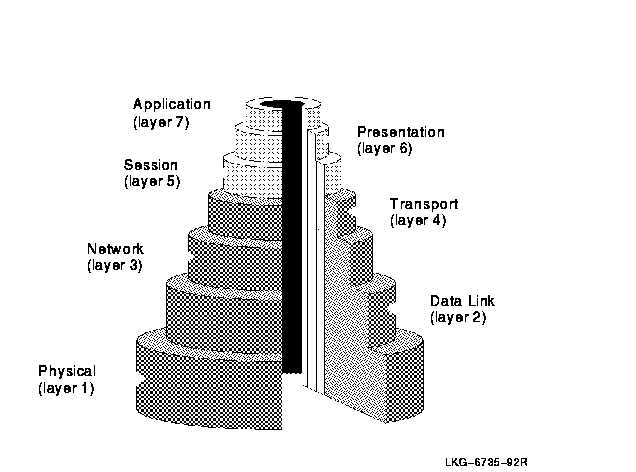
Table 3-1 lists the functions of the OSI layers.
| Layer | Name | Responsibilities |
|---|---|---|
| Upper Layers | ||
| 7 | Application | Provides for distributed processing and access; contains the application programs and supporting protocols (including File Transfer, Access, and Management (FTAM) and the Association Control Service Element (ACSE)) that use the lower layers; has no formal upper boundary, since it includes application programs and their individual user interfaces. |
| 6 | Presentation | Coordinates the conversion of data and data formats to meet the needs of the individual application processes. |
| 5 | Session | Organizes and structures the interactions between pairs of communicating application processes. |
| Lower Layers | ||
| 4 | Transport | Provides reliable, transparent transfer of data between end systems, with error recovery and flow control. |
| 3 | Network | Permits communications between network entities in open systems on a subnetwork, intermediate systems, or both. |
| 2 | Data Link | Specifies the technique for moving data along network links between defined points on the network, and how to detect and correct errors in the Physical layer. |
| 1 | Physical | Connects systems to the physical communications media. |
DNA Phase V integrates the lowest four architectural layers of OSI and DNA, while also offering the upper three layers of both DNA and OSI. Table 3-2 shows the names of the DECnet-Plus layers with the corresponding DNA Phase IV names.
| DNA Phase IV | DNA Phase V |
|---|---|
| DECnet and User Application layer | DECnet, OSI and User Application layer |
| Session Control layer | Presentation, Session layers |
| End Communications layer | Transport layer |
| Routing layer | Network layer |
| Data Link layer | Data Link layer |
| Physical Link layer | Physical layer |
3.2 Data Flow
Except for the Application layer, each layer provides a service to the
layer immediately above (its user). Every layer is
supported by all the lower layers, and adds functional value to the
service available from the layer immediately below. For example, the
Transport layer adds in-sequence delivery of data and also
retransmission of data lost by the lower layers. Figure 3-2 shows how
data flows during communications.
Figure 3-2 OSI Reference Model: Data Flow
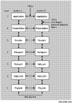
Entities within each layer on one system use the services provided by
its next lower layer to communicate with other (peer) entities on a
second system.
3.3 OSI Terminology
The Reference Model is a network design of layers that work together. Each layer is an independent and self-contained group of interconnected functions with its own purpose and protocols. Layers also provide services. Each layer uses the services provided by the layer beneath it.
For each layer, OSI has two types of international standard:
A protocol is a set of rules and procedures. Protocols govern the behavior of open systems at each layer. Some layers (for example, the Application layer) have several protocols.
A protocol machine is software that implements a particular protocol.
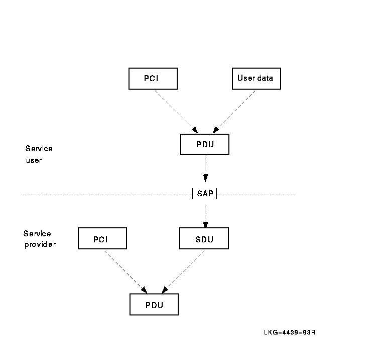
A protocol data unit (PDU) is information made up of protocol control information (PCI) from the current layer and, possibly, user data from the layer above. PDUs are exchanged between peer protocol machines using service primitives. A given service primitive can correspond to zero, one, or more PDUs. The integrity and identity of a PDU remains intact while it is being exchanged.
The underlying layer places each PDU received from the above layer into a service data unit (SDU). The SDU becomes user data in the PDU of its underlying layer. PDUs remain intact until they arrive at the protocol machine of the peer entity. The peer's protocol machine separates the PCI from user data and processes the PCI. Figure 3-3 shows the relationships among the PCI, user data, SDUs, and PDUs.
Figure 3-3 The Relationship of PDUs, User Data, and SDUs
Applications can communicate with each other only if they agree on the
protocols they both will use and the operational parameters of these
protocols. Also, exact address information is needed to indicate to
each layer of protocol where to deliver data. This required information
is encoded in a protocol stack or protocol
tower, which is a data structure for encoding address and
protocol information about a service user (application). The tower is a
protocol sequence (an ordered list of protocol identifiers for each
layer from the Network layer upward) with associated address and
protocol-specific information.
3.3.3 Dialogues
OSI protocol machines ensure that open systems can establish message exchanges, called dialogues. Though many dialogues can occur simultaneously, each dialogue is independent of other dialogues. Protocol machines cooperate to conduct a dialogue through a predictable sequence of states. The portion of a dialogue conducted at the Application layer is called an association; the portions of dialogues conducted at other layers are called connections.
Associations or connections are established between service users by
their peer service providers; for example, the Association Control
Service Element (ACSE) establishes FTAM associations. Connections use
the name of the service provider that establishes them; for example, a
connection established by Presentation for ACSE is called a
presentation connection.
3.3.4 Entities
Protocol machines operate within system-specific implementations, or processes. For every dialogue, one or more processes activate the protocol machines of each layer independently. An instance of such protocol-machine activity is called an entity. OSI entities, which are the manageable components that make up the network, relate to entities on other systems for example, a routing circuit. The relationship between processes and entities is implementation-specific.
Each entity communicates with equivalent entities on different systems,
called peer entities.
3.3.5 Services
A service is an interface provided by a service element or a layer for accessing one or more functions. An application service element (ASE) is a component that provides an application-level function. FTAM and ACSE are examples of service elements.
The service element or layer that provides a service is called a
service provider. An application program, service
element, or layer that uses a service is called the service
user.
3.3.5.1 Service Primitives
To request or receive indications of a service, peer entities exchange messages called service primitives. A service primitive carries parameter values for a specific service. There are two pairs of service primitives:
Each pair of service primitives generates only one unit of user data, a protocol data unit (PDU).
Service users and service providers originate primitives as follows:
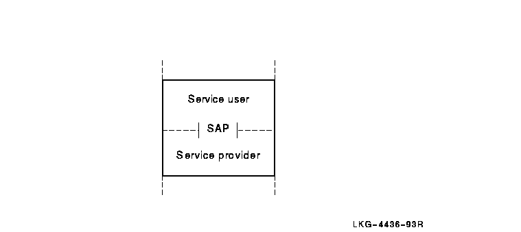
A service provider delivers services to a service user at an interface called a service access point (SAP). A SAP is the point at which an entity provides a service to a user entity in the layer above.
Figure 3-4 shows how a service user, a service provider, and a SAP interact.
Figure 3-4 Service User, Service Provider, and SAP Interaction
Except for the Application and Physical layers, SAPs exist at the boundaries of all OSI layers. SAPs are named according to the layer providing the services. For example, transport services are provided at a Transport SAP (TSAP) at the top of the Transport layer and any SAP that the Presentation layer provides is called a Presentation SAP (PSAP). Figure 3-5 illustrates SAP nomenclature.
Figure 3-5 SAPs at Different OSI Layers
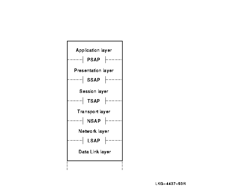
SAPs are logical constructs defined by an identifier called a SAP selector. To create a SAP, a system manager or application user defines a unique SAP selector for a specific layer. SAP selectors are the building blocks of addresses.
A given address takes the name of the uppermost SAP that contributes a selector to the address. For example, a presentation address accesses the Application layer.
A presentation address (p-address) contains one or more SAP selectors at the upper layers. The composition of a given address depends on the purpose of the address. For example, an address that allows the Transport layer to access the Application layer has SAPs at three layers: Transport, Session, and Presentation. A p-address is used for upper-layer addressing and has SAPs at four layers: Network, Transport, Session, and Presentation.
In addition, on a LAN, the Data Link layer uses the source service access point (SSAP) and the destination service access point (DSAP):
Each of the upper three layers provides services for user and application processes.
The Session layer service is used by a pair of communicating application processes to structure and control their dialogue, conducted over the transport connection.
The Presentation layer works in conjunction with the Session layer to provide a specialized data transfer service to the Application layer. It coordinates any necessary conversion of data between a pair of communicating application processes.
Because the semantics and syntax used by one application are unlikely to be the same as those used by another on a different system, the Presentation layer transfers data in a system-independent way. The data must be in a form that both applications can recognize; for example, data with floating-point numbers can pass between two systems even if each system has a different internal representation of floating-point numbers.
The Application layer contains many different
entities, including the parts of an application program that interact
with the communications environment on a system. The Application layer
has a mixture of standard protocols. Some directly support application
processes, others support those that give direct support to the
application processes, and some do both,
such as the ACSE protocol.
3.4.1 Presentation and Session Entities
Presentation and Session entities provide the Presentation and Session connections. To form an association, an OSI application entity requires a corresponding Presentation entity and Session entity. For the FTAM software, for example, these Presentation and Session entities occur within the same process as the FTAM entity.
The combined effect of the Presentation and Session entities is to manage data transfer for Application entities. For OSI applications:
The Session Control layer provides the DNA user and application
interfaces. Session Control performs address resolution and selection,
connection control, and manages transport connections on behalf of
applications. It also supports the applications environment, including
$IPC and $QIO programming interfaces.
3.5.1 Objects and Applications
The terms "object" and "application" are used differently in DECnet-Plus than in Phase IV:
The sequence of protocol identifiers in a protocol tower typically extends from the Network layer up to the DNA application. Session Control builds and maintains multiple towers for the local node object: one tower for each protocol and each address through which Session Control can access the object. A protocol tower set includes all the protocol towers that the system builds for the object.
When a DNA application on one node requests a connection to another
node, Session Control requests that DECdns provides DNA$Towers
attribute information for the remote node. Session Control compares the
tower information with the tower information it maintains for the local
node and selects a protocol tower common to both nodes. The connection
is then made automatically without a user or application needing to
know what lower-layer protocols the nodes are using.
3.5.3 Address Resolution
The Session Control layer maps the global name of the node object with a set of protocols and addresses that can be used to communicate with that node. The Session Control layer performs the following functions for address resolution:
You can autoconfigure addresses for DECnet-Plus systems, which can change over time. Session Control creates and maintains the protocol and address information in the towers in the namespace for the node object entry.
Session Control supports a RegisterObject function to maintain
the address attribute of an object entry if the underlying protocol
tower address element of the node changes. Applications can request
that Session Control perform this function for their objects.
3.5.4 Address Selection
The Session Control layer initiates a connection based on the address
of a system and the Session Control application being connected to that
system. It receives a list of common protocol towers with the
address-resolution function and looks for a set of mutually supported
protocols. It tries to make a connection using all towers in common;
the connection fails if all towers are tried and none works. The
selected protocols and address information are used for communication
with the remote system.
3.5.5 Connection Control
The Session Control layer performs connection services for Session Control applications. It requests, maintains, and disconnects or aborts transport connections. Session Control can request a connection using the destination address. It can receive a connect request, validate the access control information supplied with the request, and identify the remote application making the request. The Session Control layer sends and receives data over transport connections.
The Session Control layer forms the interface between all DNA
applications and the Transport layer. It allows use of the NSP
Transport and OSI Transport protocols.
3.5.6 DIGITAL-Supplied Session Control Layer Applications
Session Control applications in DECnet-Plus for OpenVMS provide general-purpose network services. A Session Control layer application is identified by application type, which is a discrete numeric identifier for either a user task or a DECnet-Plus program, such as file access listener (FAL). DECnet-Plus for OpenVMS uses application type numbers to enable logical link communications using the NSP Transport Service or the OSI Transport Service.
DECnet-Plus has two types of Session Control applications:
| Previous | Next | Contents | Index |