HP OpenVMS Systems Documentation |
DECnet-Plus for OpenVMS
|
| Previous | Contents | Index |
The Network Control Language (NCL) is a command line interface to the director, which interprets the input NCL commands, sends these commands to a target entity for processing, and presents the results back to the network manager.
Directors use common mechanisms to communicate with the entities they manage. The same director can manage both local and remote entities. If the managed entity resides on the local system, the director uses the local interface to access it. If the managed entity resides on a remote system, the director converts the NCL message to CMIP and sends the converted message to the entity agent on the remote system.
The management information and operations that pass between directors and entities are:
The management access relationship between a parent entity and a child entity indicates that the parent is capable of passing directives to its child entities. A parent entity is an entity that has created another entity (the child entity); a child entity is a lower class of entity that receives directives forwarded from its parent entity.
The DECnet-Plus director does not directly access the agents of local
entities. To access a local entity's management interface, the director
accesses the appropriate global node entity that is the parent
of the target local entity. That node entity forwards the
directive down the entity hierarchy; the forwarding process continues
from higher to lower entities until the correct target entity receives
the directive. The agent access point is the place of
connection between a director or a parent entity and an agent.
3.10.2.2 Management of Remote DECnet Phase IV Nodes
The DECnet-Plus network management protocol is based on DNA Common Management Information Protocol (DNA CMIP) draft standard for network management operations. CMIP is used for encoding network management operations that can be performed on an entity. CMIP permits the exchange of information between a director and an agent. CMIP supersedes the Phase IV Network Information and Control Exchange (NICE) protocol.
DECnet-Plus software supports remote management of Phase IV nodes by continuing to support Phase IV NCP and the Phase IV network management protocol (NICE).
However, Phase IV applications that have been written to create logical
links to the Phase IV Network Management Listener (NML) and then parse
the returned NICE protocol messages are not supported for managing
DECnet-Plus for OpenVMS systems. To run on a network composed of
DECnet-Plus systems, those applications must be rewritten to use
DECnet-Plus network management software and protocols. For example, the
application may be rewritten to use the DECnet-Plus CML callable
interface into network management. Also, Phase IV applications that use
NCP to configure the application need to be converted to use NCL.
3.10.2.3 Support for Phase IV NCP and the NICE Protocol
DECnet-Plus software supports remote management of DECnet Phase IV
nodes by use of NCP.EXE. This utility supports a significant range of
NCP commands. It is not designed as a replacement for NCL.
3.10.2.4 Maintenance Operation Protocol (MOP) Support
With the Maintenance Operation Protocol (MOP), you can communicate with systems that are not fully operational, for example DECnet-Plus intermediate systems. Low-level maintenance functions of MOP run directly on top of data links, such as ISO 8802-2. MOP functions are often placed in ROMs on link controllers. MOP operations include:
DECnet-Plus for OpenVMS provides enhanced support for concurrent
downline loads.
3.10.3 Configuration Procedure for DECnet-Plus for OpenVMS
The net$configure.com configuration procedure offers you several options for configuring DECnet-Plus:
$ @sys$manager:net$configure |
$ @sys$manager:net$configure basic |
$ @sys$manager:net$configure advanced |
You can also use net$configure.com to reconfigure all or some of the DECnet-Plus for OpenVMS system. Rerunning the configuration procedure modifies or replaces relevant initialization script files but does not affect running systems. You then execute the modified initialization script files to effect these changes.
The initialization scripts create and enable all required entities. Each entity is initialized through execution of a separate NCL script file. Using NCL scripts to initialize DECnet-Plus for OpenVMS systems replaces the Phase IV requirement of establishing a DECnet permanent configuration database at each node. Remote node information resides in either a local or distributed DECdns namespace.
For further information, refer to the DECnet-Plus Network Management guide.
This chapter introduces basic X.25 networking concepts and how they fit into the DECnet standards for system interconnection as illustrated in Figure 2-2. Refer to the X.25 for OpenVMS Management Guide for specific information on managing and monitoring an X.25 system as well as descriptions of specific parts of an X.25 system (call handling, templates, application filters, server and relay clients, and addressing).
X.25 is a recommendation made by the Comité Consultatif International Téléphonique et Télégraphique (CCITT). The CCITT is a United Nations committee that makes recommendations on data communications services. The CCITT has made several recommendations to ensure that different networks are compatible in their operation. Many of its recommendations have been implemented widely by major network providers.
The X.25 recommendation specifies the interface between data terminal
equipment (DTE) and data circuit-terminating equipment (DCE) for
equipment operating in the packet mode on public data networks.
4.1.1 Packet Switching Data Networks (PSDN)
Packet switching is a method of sending data across a network. In this method, data is divided into blocks, called packets, which are then sent across a network. Networks using this method are referred to as packet switching data networks (PSDNs) or X.25 networks.
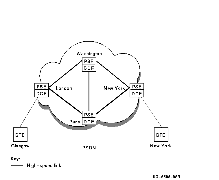
Figure 4-1 shows an example of the equipment involved in sending data across a PSDN. PSDNs are made up of packet switching exchanges (PSEs), and high-speed links that connect the PSEs. Each PSE contains data circuit-terminating equipment (DCE). The DCE is the point where all data enters and leaves a PSDN.
The user's computer that sends data to the DCE, and receives data from the DCE, is known as the data terminal equipment (DTE). Outside a PSDN, packets travel between the DTE and DCE. Inside a PSDN, packets travel between PSEs.
Figure 4-1 Packet Switching Equipment
A PSDN is either owned by a country's Postal, Telegraph, and Telephone (PTT), Authority or it is privately run. Public PSDNs can be used by anyone, on payment of connection fees and regular bills. Private PSDNs are used to serve a single body, such as a large corporation.
Public and private PSDNs can be interconnected. It is, therefore, possible to pass data packets from one DTE to another no matter where in the world the DTEs are located.
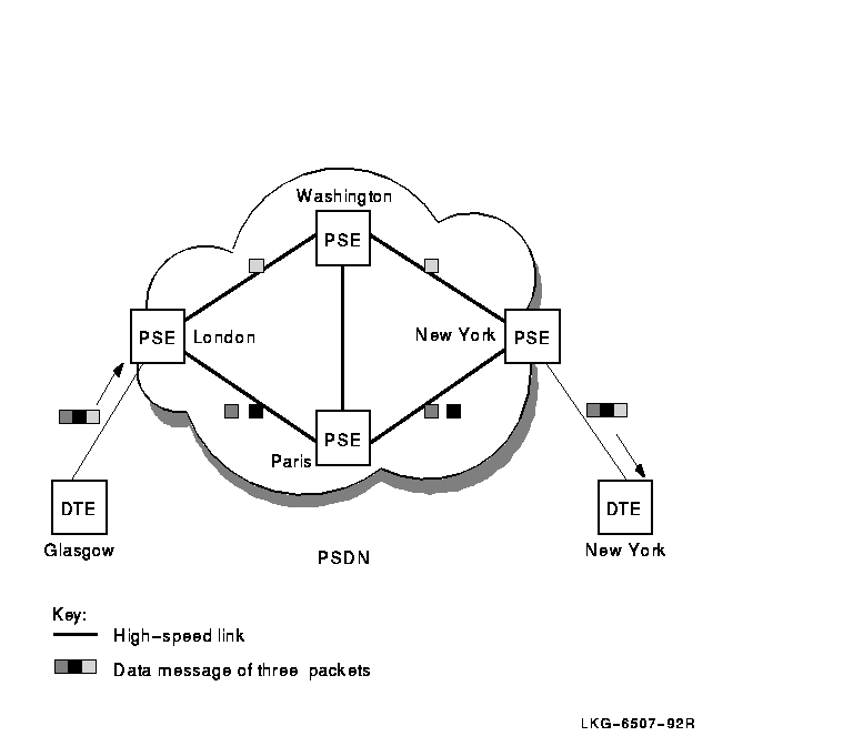
The PSDN sends each packet to its destination by the best available route at the time. The packets that make up a data message may take different routes to reach the same destination; this will occur if certain routes are busy or if there is a line failure within the PSDN. Figure 4-2 shows an example of packets traveling by different routes across a PSDN.
When the packets reach their destination, they are reassembled so that the original order of the packets in the data message is maintained.
Figure 4-2 Packets Traveling Over a PSDN
There are two types of data terminal equipment:
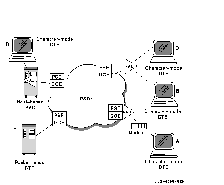
PADs allow character-mode DTEs to access PSDNs. A PAD performs the following functions:
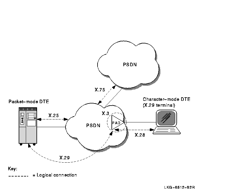
Figure 4-3 shows the following PADs:
Figure 4-3 Connecting Character-Mode DTEs to a PSDN
A protocol is a set of rules for the formatting and sequencing of data. X.25 describes three protocol levels for the interface between a DTE and a DCE:
Figure 4-4 shows the three protocol levels.
Figure 4-4 X.25 Protocol Levels
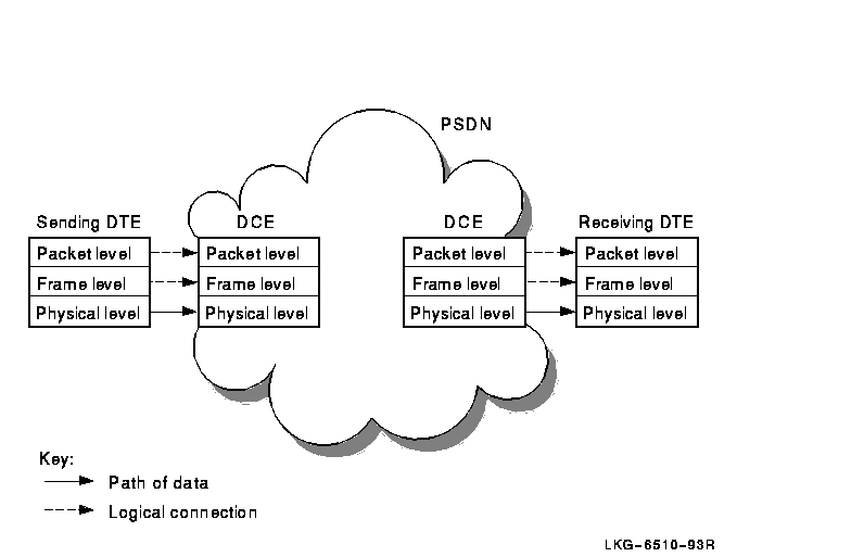
At the sending DTE, data passes down through the levels and each level adds its own control information. When it reaches the physical level, the data is transmitted to the DCE.
At the DCE, the relevant control information is removed as the data passes up through the levels. When it reaches the packet level, data is in the form of X.25 packets, which can now be sent across a PSDN.
When the packets reach the remote DCE, they pass down through the levels and pick up control information. The DCE then sends them to the receiving DTE. At the receiving DTE, the data passes up through the levels.
Each level on the DTE communicates with the corresponding level on the DCE by using the same protocols; therefore, there are logical connections between corresponding levels. They are referred to as logical connections because data is not actually transmitted until it reaches the physical level.
Two DTEs implementing X.25 protocols can exchange data in packets, regardless of the DTE manufacturer. However, once the data is re-assembled in its original format, the receiving DTE may not be able to interpret the message. In this case, additional software may be required to make the data meaningful to the receiving DTE.
4.2.1 Packet Level
This level defines the procedures for formatting packets, sequencing
packets, and establishing virtual circuits. Virtual circuits are the
logical connections between two DTEs (see Section 4.4.2.1).
Most packets contain user data, but some are for control purposes.
Control packets are used for functions such as initiating and
terminating virtual circuits between two DTEs and for interrupt
messages.
The amount of user data allowed in a packet is known as the packet size. The maximum amount of user data allowed in a packet is set by the PSDN you use. A typical packet size is 128 bytes.
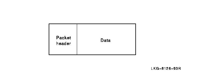
Each packet (refer to Figure 4-5) consists of a packet header followed by user data or control information.
Figure 4-5 Structure of a Packet
This level initiates communications between the DTE and the DCE and ensures that data is transferred between DTE and DCE without errors.
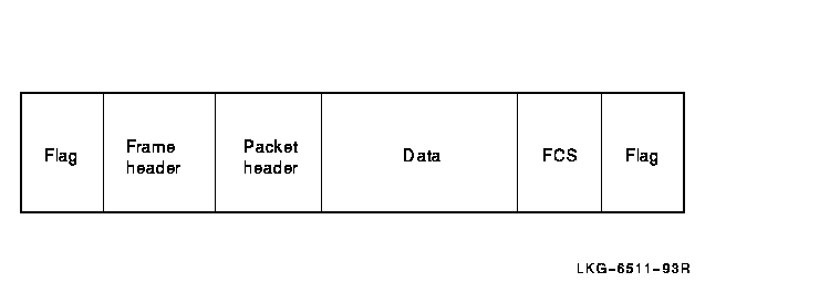
At this level each packet is enclosed within a frame. Each frame consists of:
Figure 4-6 shows the structure of a typical frame.
Figure 4-6 Structure of a Frame
This level defines the mechanical and electrical connections between a
DTE and a DCE. It specifies electrical characteristics, data
transmission speeds, and connector types.
4.3 Implemented Standards
X.25 is a CCITT recommendation that describes a standard for connecting to packet switching networks. The lower three layers of the OSI Reference Model correspond to the three levels in the Comité Consultatif International Téléphonique et Télégraphique (CCITT) X.25 recommendation.
The X.25 standard describes the protocols for the DTE-DCE interface.
4.3.1 Related CCITT Standards
The X.25 recommendation describes only those protocols involved in the DTE-DCE interface to packet switching networks. There are several other CCITT recommendations that are relevant to packet switching, including:
Figure 4-7 illustrates the main packet switching recommendations.
Figure 4-7 CCITT Packet-Switching Recommendations
DECnet-Plus for OpenVMS also implements the following PSDN-related standards from OSI:
4.4 How Connections Are Made and Data Is Transferred
To establish a call and transfer data between DTEs via a PSDN, physical
and logical connections must be made between the calling and called DTE.
4.4.1 Physical Connections
To transfer data, the DTE and DCE must be connected. This connection can take many forms but, in general, the connection is made using a physical line. Two types of line can be used to connect a DTE and a DCE:
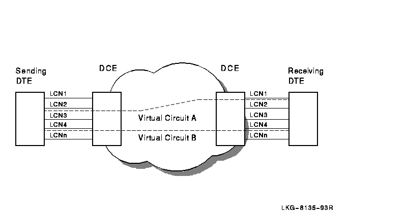
The physical line between a DTE and a DCE is divided into a number of logical channels. Logical channels allow many virtual circuits to exist on the physical line. Each logical channel is identified by a logical channel number (LCN), contained in the packet header of every packet sent across a PSDN.
Before data can be sent across a PSDN, a virtual circuit must be established between a logical channel at the calling DTE and a logical channel at the called DTE. The circuits are referred to as "virtual" because a number of virtual circuits may use the same physical circuit to transmit packets from the calling DTE to the called DTE.
It is important to realize that the logical channel used between a DTE and DCE only has local significance. It is the responsibility of the PSDN to map the logical channels used by the calling and called DTEs into an end-to-end virtual circuit. This means that although a virtual circuit has end-to-end significance between the DTEs, different logical channels can be used by the virtual circuit on each side of the PSDN.
This concept is illustrated in Figure 4-8 in which two virtual circuits are depicted. Virtual Circuit A establishes an end-to-end connection using LCN 2 between the calling DTE and its associated DCE, and LCN 1 between the called DTE and its associated DCE. Similarly, Virtual Circuit B establishes an end-to-end connection using LCN 4 on both sides of the PSDN.
Figure 4-8 Virtual Circuits Versus Logical Channels
| Previous | Next | Contents | Index |