HP OpenVMS Systems Documentation |
HP BASIC for OpenVMS
|
| Previous | Contents | Index |
This chapter describes how HP BASIC represents data stored in memory.
The following sections discuss four types of data representation:
integer, float, decimal, and string.
17.1 Integer Format
There are four ways in which integer data can be represented, depending
on the size of the data to be stored: byte, word, longword, and
quadword. Negative integer values are stored in two's complement
format. The following sections describe each of these formats.
17.1.1 Byte-Length Integer Format
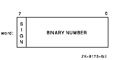
Byte-length integers are in the range -128 to 127 and are stored as 1 byte (8 bits), starting on an arbitrary byte boundary. Bits are labeled from the right, 0 to 7, as in Figure 17-1.
Figure 17-1 Byte-Length Integer Format
Word-length integers are in the range -32768 to 32767 and are stored as two contiguous bytes, starting on an arbitrary byte boundary. Bits are labeled from the right, 0 to 15, as in Figure 17-2.
Figure 17-2 Word-Length Integer Format

Longword integers are stored as four contiguous bytes, starting on an arbitrary byte boundary. Values are in the range -2147483648 to 2147483647. See Figure 17-3.
Figure 17-3 Longword Integer Format

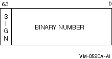
Quadword integers are stored as eight contiguous bytes, starting on an arbitrary byte boundary. Values are in the range -9223372036854775808 to 9223372036854775807. See Figure 17-4.
Figure 17-4 Quadword Integer Format
The compiler incorrectly gives an integer overflow message when the most negative integer constants are used, as follows:
BYTE -128% WORD -32768% LONG -2147483648% QUAD -9223372036854775808% |
The workaround is to use the appropriate expression from the following:
BYTE -127% - 1% WORD -32767% - 1% LONG -2147483647% - 1% QUAD -9223372036854775807% - 1% |
Real numbers, like integers, can be represented in varying formats,
depending on the size of the data to be stored. These formats include
SINGLE floating-point, DOUBLE floating-point, GFLOAT floating-point,
SFLOAT floating-point, TFLOAT floating-point, XFLOAT floating-point,
and packed DECIMAL format. The following sections describe each of
these formats.
17.2.1 SINGLE Floating-Point Number Format (F_floating)
F_floating (single-precision) floating-point numbers are stored as four contiguous bytes, starting on an arbitrary byte boundary. Bits are labeled from the right, 0 to 31.
The format for single-precision is sign magnitude, with bit 15 the sign bit, bits 14 to 7 an excess-128 binary exponent, and bits 6 to 0 and 31 to 16 a normalized 24-bit fraction with the redundant, most significant fraction bit not represented. See Figure 17-5 for the format. The 8-bit exponent field encodes the values from 0 to 255, inclusively.
An exponent value of 0 together with a sign bit of 0 indicates that the F_floating number has a value of 0. Exponent values from 1 to 255 indicate true binary exponents of -127 to 127. An exponent value of 0, together with a sign bit of 1, is taken as reserved. (Floating-point instructions processing a reserved operand take a reserved operand fault.) The magnitude of an F_floating number is in the approximate range .29 * 10-38 to 1.7 * 1038. The precision of an F_floating number is approximately one part in 223 (approximately 7 decimal digits).
Figure 17-5 Single-Precision Real Number Format

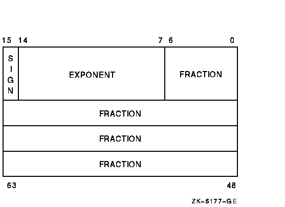
Double-precision real number format consists of eight contiguous bytes, starting on an arbitrary byte boundary. Bits are labeled from the right, 0 to 63, as in Figure 17-6. The form of a D_floating number is identical to the F_floating form, except for an additional 32 low-significance fraction bits. Within the fraction, bits increase in significance from 48 to 63, 32 to 47, 16 to 31, and 0 to 6. The exponent conventions and approximate range of values are the same for both D_floating and F_floating numbers. The precision of a D_floating number is approximately one part in 255 (approximately 16 decimal digits).
Figure 17-6 Double-Precision Real Number Format
In Alpha BASIC, it is possible to lose three binary digits of precision in arithmetic operations when performing operations on D_floating double-precision floating-point data. For each arithmetic operation, the data is converted to G_floating first, the operation is performed in G_floating, and the result is converted back to D_floating when the operation is complete.
Because most floating-point values cannot be represented exactly in binary, they are susceptible to rounding. I64 BASIC and the Itanium hardware use T_floating representation in place of D_floating representation. Alpha BASIC and the Alpha system hardware use G_floating representation in place of the D_floating representation. Thus, the behavior of floating-point computations and comparisons can be different from what you expect. |
The G_floating floating-point number format consists of eight contiguous bytes, starting on an arbitrary byte boundary, as shown in Figure 17-7. Bits are labeled from the right, 0 to 63. The form of a G_floating number is sign magnitude with bit 15 the sign bit, bits 14 to 4 an excess-1024 binary exponent, and bits 3 to 0 and 63 to 16 a normalized 53-bit fraction with the redundant most significant fraction bit not represented.
Within the fraction, bits increase in significance from 48 to 63, 32 to 47, 16 to 31, and 0 to 3. The 11-bit exponent field encodes the values 0 to 2047.
An exponent value of 0 together with a sign bit of 0 indicates that the G_floating number value is 0. Exponent values from 1 to 2047 indicate true binary exponents from -1023 to 1023. The value of a G_floating number is in the approximate range .56 * 10-308 to .9 * 10308; the precision is approximately one part in 252 (approximately 15 decimal digits). Note that both double and G_floating formats require 8 bytes. The G_floating format provides a greater range, but less precision than double-precision format.
Figure 17-7 GFLOAT Floating-Point Number Format

The S_floating floating-point number format consists of four contiguous bytes, starting on an arbitrary byte boundary, as shown in Figure 17-8. Bits are labeled from the right, 0 to 31. The form of an S_floating number is sign magnitude with bit 31 the sign bit, bits 30 to 23 an excess-127 binary exponent, and bits 22 to 0 a normalized 24-bit fraction with the redundant most significant fraction bit not represented unless the exponent is 0. If the exponent is 0, a nonzero fraction represents an unnormalized 23-bit fraction.
An exponent value of 0 together with a fraction value of 0 and a sign bit of 0 indicates that the S_floating number value is 0. Exponent values from 1 to 254 indicate true binary exponents from -127 to 127. The value of an S_floating number is in the approximate range 1.175 * 10-38 to 3.402 * 1038; the precision is approximately one part in 223 (approximately 7 decimal digits). Note that S_floating format provides approximately the same range and precision as F_floating format.
Figure 17-8 SFLOAT Floating-Point Number Format

The T_floating floating-point number format consists of eight contiguous bytes, starting on an arbitrary byte boundary, as shown in Figure 17-9. Bits are labeled from the right, 0 to 63. The form of a T_floating number is sign magnitude with bit 63 the sign bit, bits 62 to 52 an excess-1023 binary exponent, and bits 51 to 0 a normalized 53-bit fraction with the redundant most significant fraction bit not represented unless the exponent is 0. If the exponent is 0, a nonzero fraction represents an unnormalized 52-bit fraction.
An exponent value of 0 together with a fraction value of 0 and a sign bit of 0 indicates that the T_floating number value is 0. Exponent values from 1 to 2046 indicate true binary exponents from -1023 to 1023. The value of a T_floating number is in the approximate range 2.225 * 10-308 to 1.797 * 10308; the precision is approximately one part in 252 (approximately 15 decimal digits). Note that T_floating format provides approximately the same range and precision as G_floating format.
Figure 17-9 TFLOAT Floating-Point Number Format

The X_floating floating-point number format consists of sixteen contiguous bytes, starting on an arbitrary byte boundary, as shown in Figure 17-10. Bits are labeled from the right, 0 to 127. The form of an X_floating number is sign magnitude with bit 127 the sign bit, bits 126 to 112 an excess-16383 binary exponent, and bits 111 to 0 a normalized 113-bit fraction with the redundant most significant fraction bit not represented unless the exponent is 0. If the exponent is 0, a nonzero fraction represents an unnormalized 112-bit fraction.
An exponent value of 0 together with a fraction value of 0 and a sign bit of 0 indicates that the X_floating number value is 0. Exponent values from 1 to 32766 indicate true binary exponents from -16383 to 16383. The value of an X_floating number is in the approximate range 3.362 * 10-4932 to 1.189 * 104932; the precision is approximately one part in 2112 (approximately 33 decimal digits). Note that X_floating format provides approximately the same range and precision as H_floating format.
Figure 17-10 XFLOAT Floating-Point Number Format

The DECIMAL data type is useful for storing numbers with a fixed decimal point. DECIMAL numbers are stored as a precise representation of the value stored within the constraints of the specified number of fractional digits. A packed decimal string is a contiguous sequence of bytes in memory. The address A and length L are sufficient to specify a packed decimal string, but note that L is the number of digits, not bytes, in the string. Each byte of a packed decimal string is divided into two 4-bit fields (nibbles), each of which must contain decimal digits, except the low nibble of the last byte, which must contain a sign. The representation for the digits or signs is shown in the following table:
| Digit or Sign | Decimal | Hexadecimal |
|---|---|---|
| 0 | 0 | 0 |
| 1 | 1 | 1 |
| 2 | 2 | 2 |
| 3 | 3 | 3 |
| 4 | 4 | 4 |
| 5 | 5 | 5 |
| 6 | 6 | 6 |
| 7 | 7 | 7 |
| 8 | 8 | 8 |
| 9 | 9 | 9 |
| + | 10,12,14, or 15 | A,C,E, or F |
| -- | 11 or 13 | B or D |
Despite the options, the preferred sign representation is 12 for positive and 13 for negative. The length L is the number of digits in the packed decimal string (not counting the sign) and must be in the range 1 to 31. If the number of digits is odd, the digits and the sign fit into ((L/2) + 1) bytes; when the number of digits is even, an extra 0 digit must appear in the high nibble (bits 7 to 4) of the first byte.
The address A of the string specifies the byte of the string containing the most significant digit in its high nibble. Digits of decreasing significance are assigned to increasing byte addresses and from high nibble to low nibble within a byte.
Note that the decimal point is specified by the descriptor for the
packed decimal string. See Section 17.6 for more information about
packed decimal string descriptions.
17.4 String and Array Descriptor Format
A descriptor is an OpenVMS data structure that
describes how to access data in memory. A descriptor can also pass
information about a paramater with that parameter. The following
sections describe the formats for fixed-length and dynamic string
descriptors.
17.4.1 Fixed-Length String Descriptor Format
A fixed-length string descriptor consists of two longwords.
The first word of the first longword contains a value equal to the string's length. The third byte contains 14 (0E hexadecimal---the OpenVMS code describing an ASCII character string). The fourth byte contains 1.
The second longword is a pointer containing the address of the string's first byte. See Figure 17-11. For more information, see the OpenVMS Calling Standard.
Figure 17-11 Fixed-Length String Descriptor Format

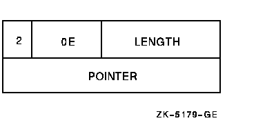
A dynamic string descriptor consists of two longwords.
The first word of the first longword contains a value equal to the string's length. The third byte contains 14 (0E hexadecimal---the OpenVMS code describing an ASCII character string). The fourth byte contains 2.
The second longword is a pointer containing the address of the string's first character. See Figure 17-12. For more information, see the OpenVMS Calling Standard.
Figure 17-12 Dynamic String Descriptor Format
HP BASIC creates DSC$K_CLASS_NCA, a noncontiguous class array
descriptor. For more information, see the OpenVMS Calling
Standard.
17.6 Decimal Scalar String Descriptor (Packed Decimal String Descriptor)
A single descriptor form gives decimal size and scaling information for both scalar data and simple strings. See Figure 17-13 for more information.
Figure 17-13 Decimal Scalar String Descriptor
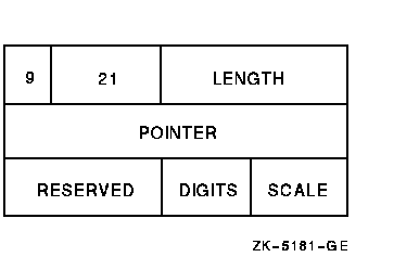
For packed decimal strings, the length field contains the number of 4-bit digits (not including the sign). The pointer field contains the address of the first byte in the packed decimal string. The scale field contains a signed power-of-ten multiplier to convert the internal form to the external form. For example, if the internal number is 123 and the scale field is +1, then the external number is 1230.
Part 3 describes BASIC features available on OpenVMS systems including advanced file input and output, libraries and shareable images, and error messages.
This chapter describes the more advanced I/O features available in HP BASIC. The following topics are presented:
When you do not specify a file name in the OPEN statement, the I/O you perform is said to be device-specific. This means that read and write operations (GET and PUT statements) are performed directly to or from the device. For example:
OPEN "MTA2:" FOR OUTPUT AS FILE #1 OPEN "MTA1:PARTS.DAT" FOR INPUT AS FILE #2, SEQUENTIAL |
Because the file specification in the first line does not contain a file name, the OPEN statement opens the tape drive for device-specific I/O. The second line opens an ANSI-format tape file using RMS because a file name is part of the file specification.
The following sections describe both I/O to ANSI-format magnetic tapes and device-specific I/O to magnetic tape, unit record, and disk devices.
For more information about I/O to RMS disk files, see Chapter 13.
18.1 RMS I/O to Magnetic Tape
HP BASIC supports I/O to ANSI-formatted magnetic tapes. When
performing I/O to ANSI-formatted magnetic tapes, you can read or write
to only one file on a magnetic tape at a time, and the files are not
available to other users. ANSI tape files are RMS sequential files.
18.1.1 Allocating and Mounting a Tape
You should allocate the tape unit to your process before starting file operations. For example:
$ ALLOCATE MT1: |
This command assigns tape drive MT1: to your process. You must also set the tape density and label with the MOUNT command. Optionally, you can specify a logical name to assign to the device, in this case, TAPE.
$ MOUNT/DENSITY=1600 MT1: VOL001 TAPE |
When mounting a TK50, you cannot specify a density.
If the records do not specify the size of the block (no value in HDR 2), specify the BLOCKSIZE as part of the MOUNT command. For example:
$ MOUNT/DENSITY=1600/BLOCKSIZE=128 MT1: VOL020 TAPE |
Alternatively, you can use the $MOUNT system service to mount tapes.
18.1.2 Opening a Tape File for Output
To create and open a magnetic tape file for output, use the OPEN statement. The following statement opens the file PARTS.DAT and writes 256-byte records that are blocked four to a physical tape block of 1024 bytes:
OPEN "MT1:PARTS.DAT" FOR OUTPUT AS FILE #2%, SEQUENTIAL FIXED,  &
               RECORDSIZE 256%, BLOCKSIZE 4%
|
Specifying FIXED record format creates ANSI F format records. Specifying VARIABLE creates ANSI D format records. If you do not specify a record format, the default is VARIABLE.
If you do not specify a block size, HP BASIC defaults to one
record per block. For small records, this can be inefficient; the tape
will contain many interrecord gaps.
18.1.3 Opening a Tape File for Input
To open an existing magnetic tape file, you also use the OPEN statement. For example, the following statement opens the file PAYROLL.DAT. If you do not specify a record size or a block size, HP BASIC defaults to the values in the header block. If you do not specify a record format, HP BASIC defaults to the format present in the header block (ANSI F or ANSI D). You must specify ACCESS READ if the tape is not write-enabled. For example:
100    OPEN "TAPE:PAYROLL.DAT" FOR INPUT AS FILE #4%
               ,ACCESS READ
|
The NOREWIND statement positions the tape for reading and writing as follows:
For example, the following statement opens PAYROL.DAT after advancing the tape to the logical end-of-tape. If you omit NOREWIND, the file opens at the beginning of the tape, logically deleting all subsequent files.
OPEN "MT1:PAYROL.DAT" FOR OUTPUT AS FILE #1% &
          ,ORGANIZATION SEQUENTIAL, NOREWIND
|
Note that you cannot specify REWIND; to avoid rewinding the tape, omit the NOREWIND keyword.
| Previous | Next | Contents | Index |