 |
Upgrading Privileged-Code Applications on OpenVMS Alpha and
OpenVMS I64 Systems
4.5.2 Direct I/O
- The caller's virtual address for the buffer is used only in FDT context.
- Most of the driver identifies buffer start by IRP$L_SVAPTE and IRP$L_BOFF.
- Driver "layering" in start I/O or fork environments.
- Most drivers use either OpenVMS-supplied upper-level FDT routines or FDT
support routines.
- The moving of the page tables has a significant impact:
- Only the current process's PPTEs are available at any given
time.
This is called the "cross-process PTE access" problem.
- A 64-bit address is required to access page table entries in page table
space: process, global, and system PTEs.
- Because "SVAPTE, BOFF, BCNT" are used in many device drivers,
the impact of 1 and 2 is not insignificant.
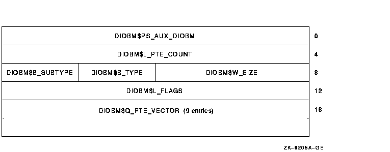
4.5.3 Direct I/O Buffer Map (DIOBM)
Figure 4-3 shows the DIOBM data
structure.
Figure 4-3 Direct I/O Buffer Map Data Structure

- Use PTE vector in DIOBM for buffers up to 64 Kb
- Use "secondary" DIOBM for buffers up to 5.2 Mb
- Use PTE window method with DIOBM for larger buffer
- DIOBM embedded in IRP, IRPE, VCRP, DCBE
- MMG_STD$IOLOCK_BUF replaces MMG_STD$IOLOCK
- New DIOBM routines; for example IOC_STD$FILL_DIOBM
- Also of interest to LAN VCI clients
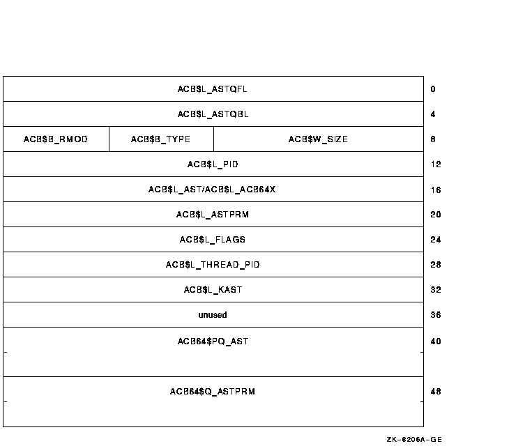
4.5.4 64-Bit AST
Figure 4-4 shows a 64-Bit AST.
Figure 4-4 64-Bit AST

| ACB$B_RMOD |
New ACB$V_FLAGS_VALID bit (last spare bit) |
| |
|
| ACB$L_FLAGS |
Contains ACB$V_64BITS bit (was filler space) |
| |
|
| ACB$L_ACB64X |
Byte offset to ACB64X structure |
- Both ACB and ACB64X formats are supported.
- ACB packets are self-identifying.
- An ACB64 is an ACB with an immediate ACB64X.
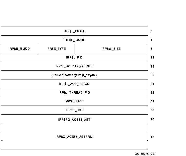
4.5.5 64-Bit ACB Within the IRP
An embedded ACB64 at the start of the IRP is shown in Figure
4-5.
Figure 4-5 Embedded ACB64

An IRP created by the $QIO system service uses the ACB64 layout unconditionally.
| IRP$B_RMOD |
New ACB$V_FLAGS_VALID bit always set |
| |
|
| IRP$L_ACB_FLAGS |
New ACB$V_64BITS bit always set |
| |
|
| IRP$L_ACB64X_OFFSET |
Contains hex 28 |
4.5.6 I/O Function Definitions
I/O functions are defined as follows:
- Direct I/O, raw data transfer
Functions in this category are implemented as direct I/O operations and transfer
raw data from the caller's buffer to the device without significant alteration
or interpretation of the data.
- Direct I/O, control data transfer
Functions in this category are implemented as direct I/O operations and transfer
control information from the caller's buffer to the device driver. The
device driver usually interprets the data or uses it to control the operation
of the device.
Usually these functions do not support 64-bit addresses. In contrast to the
raw data transfers, control data transfers tend to be smaller and are invoked
less frequently. Thus, there is less need to be able to store such data in
a 64-bit addressable region. The only area impacted in the driver are the
corresponding FDT routines. However, control data often introduces the problem
of embedded 32-bit pointers.
- Buffered I/O, raw data transfer
Functions in this category are implemented as buffered I/O operations by
the device driver but are otherwise the same type of raw data transfer
from the caller's buffer as the first category.
- Buffered I/O, control data transfer
Functions in this category are implemented as buffered I/O operations by
the device driver but are otherwise the same type of control data transfer
from the caller's buffer as the second category.
- Control operation, no data transfer, with parameters
Functions in this category control the device and do not transfer any data
between a caller's buffer and the device. Since there is no caller's buffer
it does not matter whether the function is designated as a buffered or
direct I/O function. The control operation has parameters that are specified
inp1 throughp6 however
these parameters do not point to a buffer.
- Control operation, no data transfer, with no parameters
Functions in this category control the device and do not transfer any data
between a caller's buffer and the device. Since there is no caller's buffer
it does not matter whether the function is designated as a buffered or
direct I/O function. In addition, there are no parameters for these functions.
Table 4-3 summarizes the I/O functions
described in this section.
Table 4-3 Guidelines for 64-Bit Support by I/O Function
| Function Type |
64-Bits |
Area of Impact |
| |
|
|
| Direct I/O, raw data transfer |
Yes |
FDT only |
| |
|
|
| Direct I/O, control data transfer |
No |
FDT only |
| |
|
|
| Buffered I/O, raw data transfer |
No/yes |
Entire driver, new BUFIO packet |
| |
|
|
| Buffered I/O, control data transfer |
No |
Entire driver, new BUFIO packet |
| |
|
|
| Control, no data transfer, param |
No |
Entire path but usually simple |
| |
|
|
| Control, no data transfer, no params |
Moot |
None |
| |
|
|
4.6 64-Bit Support in Example Driver
This section summarizes changes made to the example device driver (LRDRIVER.C)
to support 64-bit buffer addresses on all I/O functions.
This sample driver is available in the SYS$EXAMPLES directory.
- All functions are declared as capable of supporting a 64-bit P1 parameter.
- The 64-bit buffered I/O packet header defined by bufiodef.h is used instead
of a privately defined structure that corresponds to the 32-bit buffered
I/O packet header.
- The pointer to the caller's set mode buffer is defined as a 64-bit pointer.
- IRP$Q_QIO_P1 is used instead of IRP$L_QIO_P1.
- The EXE_STD$ALLOC_BUF_64 routine is used instead of EXE_STD$DEBIT_BYTCNT_ALO
to allocate the buffered I/O packet.
No infrastructure changes were necessary to this driver. The original version
could have been simply recompiled and relinked and it would have worked correctly
with 32-bit buffer addresses.
|


