The OpenVMS operating system uses the Maintenance Operations
Procedure (MOP) protocol to boot satellite nodes. MOP protocol support
is provided by either the LANACP process controlled by the LANCP utility
or by DECnet software controlled by the NCP or NCL utilities. You
must specify the name of the satellite's system disk using LANCP,
NCP, or NCL commands (depending on which you are using to boot satellites).
If the system disk is shadowed, the commands nust specify the name
of the virtual unit or the virtual unit logical name rather than the
name of any physical unit.
The MOP server accesses the system disk shadow
set (using the virtual unit defined) to perform downline load operations
to the satellite. These operations include downline loading the physical
boot device name to the satellite. When downline loading is complete,
the satellite is able to connect to an MSCP server and access the
physical boot device directly. The satellite's shadowing parameters
are then used in the same way as a non-satellite node.
You can use the SYS$MANAGER:CLUSTER_CONFIG_LAN.COM procedure
or the SYS$MANAGER:CLUSTER_CONFIG.COM procedure to set MOP server,
MSCP server, and satellite parameters automatically. When configuring
satellite nodes with the cluster configuration command procedure,
you can specify a shadowed system disk virtual unit as the satellite's
system disk. The cluster configuration command procedure then automatically
sets the satellite's system parameters SHADOW_SYS_DISK and SHADOW_SYS_UNIT
for you. The values of these parameters are transferred automatically
to the system parameter file ALPHAVMSSYS.PAR
for Alpha satellites. (See the HP OpenVMS Cluster Systems manual for
more information about using this command procedure.)
Example 3-3 shows
the commands to enter to display the LANCP satellite database entries.
Example 3-3 LANCP Database Example of a Satellite Node
$MCR LANCP
LANCP>LIST DEVICE/MOPDLL

Device Listing, permanent database:
--- MOP Downline Load Service Characteristics ---
Device    State   Access Mode      Client            Data Size
------    -----   -----------      ------            ---------
ESA0    Disabled NoExlusive  NoKnownClientsOnly     246 bytes
FCA0    Disabled NoExlusive  NoKnownClientsOnly     246 bytes

LANCP>EXIT |
For DECnet--Plus commands, see the DECnet--Plus documentation.
Example 3-4 shows the NCP commands you must enter on a MOP server to display
a satellite DECnet database entry. Note that the load assist parameter
displays the shadow set virtual unit name that downline loads the
satellite node HIWAY1. Example 3-4 uses an explicit virtual unit name. However, you might prefer to
use a logical name that translates to the virtual unit.
Example 3-4 DECnet Database Example of a Satellite Node
$MCR NCP
NCP>SHOW NODE HIWAY1 CHAR
Node Volatile Characteristics as of 12-MAR-2000 14:53:59

Remote node =   19.891 (HIWAY1)

Hardware address         = 03-03-03-03-03-BC
Tertiary loader          = SYS$SYSTEM:TERTIARY_VMB.EXE
Load Assist Agent        = SYS$SHARE:NISCS_LAA.EXE
Load Assist Parameter    = DSA1:

NCP>EXIT |
You may need to adjust the settings of the SHADOW_MBR_TMO
and SHADOW_MAX_COPY parameters on satellite nodes. These parameters
are not automatically set by the cluster configuration command procedure.
See “Volume Shadowing Parameters ” for
more information.
The cluster configuration command procedure automatically
enables shadowing on satellite nodes when you want to shadow the system
disk. If you do not want to shadow the system disk but need to enable
shadowing, you must do so manually after the cluster configuration
command procedure completes. Set shadowing parameters in the satellite
node's MODPARAMS.DAT file and execute AUTOGEN as described in “Volume Shadowing Parameters ” and in “Setting System Parameters ”.
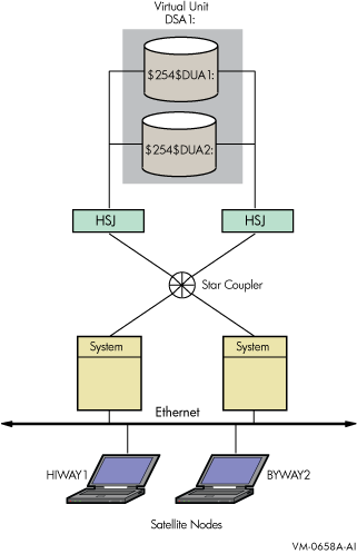
Figure 3-1 shows two satellite nodes with shadowed system disk volumes located
in an OpenVMS Cluster system configuration. In this configuration,
the devices $254$DUA1 and $254$DUA2 make up a two-member shadow set.
The satellites HIWAY1 and BYWAY2 access shadow set members across
the Ethernet via the MSCP servers in the two boot nodes.
When a satellite node in Figure 3-1 is booted, the boot
node (MOP server) downline loads initial bootstrap code from the virtual
unit DSA1. The boot node points the satellite to use either $254$DUA1
or $254$DUA2 as a boot device for the remainder of the boot process. Note that the boot node must
have the virtual unit mounted. The satellite then forms the system
disk shadow set locally according to the shadow set membership information
stored in the SCB on the boot device.
The following SHOW DEVICES command displays how
the shadow set appears after the satellite node HIWAY1 is booted.
In this example, the physical disk devices are accessed through the
MSCP server node BTNODE.
Device             Device         Error  Volume   Free    Trans  Mnt
Name               Status         Count  Label    Blocks  Count  Cnt

DSA1:              Mounted         0     MYVOLUME 181779  194    37
$254$DUA1:(BTNODE) ShadowSetMember 0 (member of DSA1:)
$254$DUA2:(BTNODE) ShadowSetMember 0 (member of DSA1:)
$ |