| Previous | Contents | Index |
The PLC-3 family supports the following addressing syntaxes:
Section 3.3.2.1 and Section 3.3.2.2 describe these addressing syntaxes.
3.3.2.1 PLC-3 Data Table Addressing
The structure of a legal data table address for the PLC-3 differs depending on the table that is being addressed. The PLC-3 supports the following data table sections:
I - Input
O - Output
C - Counter
T - Timer
A - ASCII
B - Binary
D - Decimal
F - Floating-Point
H - High-Order Integer
N - Integer
S - Status
P - Pointer
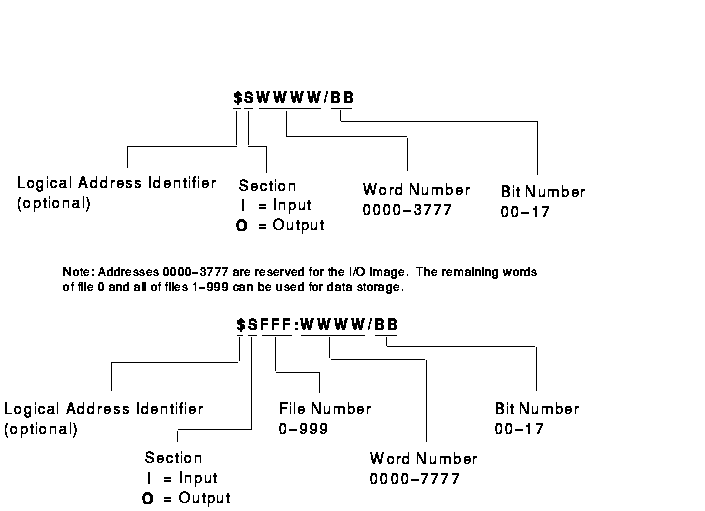
Figure 3-2 shows the structure of a legal I/O data table address for the PLC-3.
Table 3-8 shows examples of legal I/O data table addresses for the PLC-3.
Figure 3-2 PLC-3 I/O Data Table Address Format

| Example Address | MMS Type1 | Description |
|---|---|---|
| I20 | UNSIGNED_16 | Input image rack 2 group 0 octal |
| I377 | INTEGER_16 | Input image rack 37 group 7 octal |
| I1:1777/17 | BIT_STRING | Bit 17 of word 1777 octal in file 1 decimal |
| $O33:77/1 | BIT_STRING | Bit 1 of word 77 octal in file 33 decimal |
| O99:167 | INTEGER_16 | Word 167 octal in file 99 decimal |
| I0 | Array of 10 UNSIGNED_16 | Ten words beginning at rack 0 group 0 |
| Previous | Next | Contents | Index |