| Previous | Contents | Index |
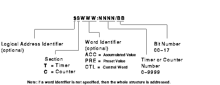
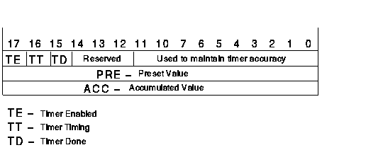
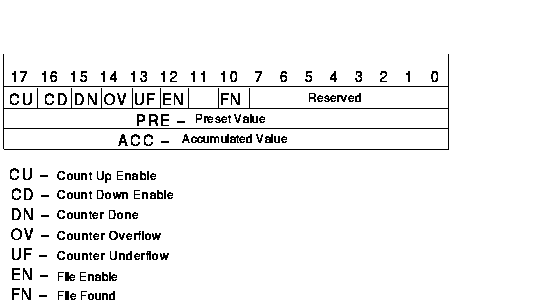
Figure 3-3 shows the structure of a legal Timer or Counter data table address for the PLC-3. Figure 3-4 shows a PLC-3 Timer structure. Figure 3-5 shows a PLC-3 Counter structure.
Table 3-9 shows examples of legal Timer or Counter data table addresses for the PLC-3.
Figure 3-3 PLC-3 Timer and Counter Data Table Address Format

Figure 3-4 PLC-3 Timer Structure

Figure 3-5 PLC-3 Counter Structure

| Example Address | MMS Type1 | Description |
|---|---|---|
| $TACC20 | UNSIGNED_16 | Timer 20 accumulated value |
| CPRE:91 | INTEGER_16 | Counter 91 preset value |
| TCTL:20/17 | BIT_STRING | Timer 20 Timer Enable bit 2 |
| T20.TD | BIT_STRING | Timer 20 Timer Done bit 2 |
| C5 |
Structure
3
UNSIGNED_16 UNSIGNED_16 UNSIGNED_16 |
All of counter 5.
Control Preset value Accumulated value |
| Previous | Next | Contents | Index |