| Previous | Contents | Index |
Figure 3-13 shows the structure of a legal Timer, Counter, Control, SFC Status, Block-Transfer Control, Token Data, ASCII String, PID Control or Message Control data table address for the PLC-5.
Figure 3-14 shows a PLC-5 Timer structure.
Figure 3-15 shows a PLC-5 Counter structure.
Figure 3-16 shows a PLC-5 Control structure.
Figure 3-17 shows a PLC-5 SFC Status structure.
Figure 3-18 shows a PLC-5 Block-Transfer Control structure.
Figure 3-19 shows a PLC-5 Token Data structure.
Figure 3-20 shows a PLC-5 ASCII String structure.
Figure 3-21 shows a PLC-5 PID Control structure.
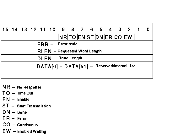
Figure 3-22 shows a PLC-5 Message Control structure.
Table 3-16 shows examples of legal Timer, Counter, Control, SFC Status, Block-Transfer Control, Token Data, ASCII String, PID Control and Message Control data table addresses for the PLC-5.
Figure 3-13 PLC-5 Timer, Counter, Control, SFC Status, Block-Transfer Control, Token Data, ASCII String, PID Control and Message Control Data Table Address Format
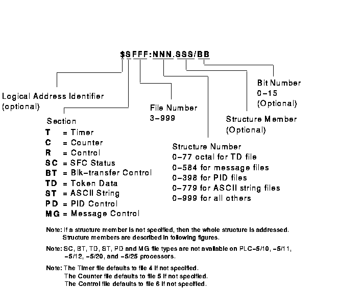
Figure 3-14 PLC-5 Timer Structure
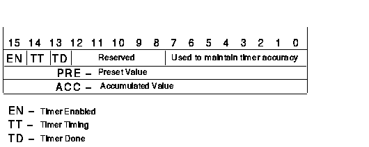
Figure 3-15 PLC-5 Counter Structure
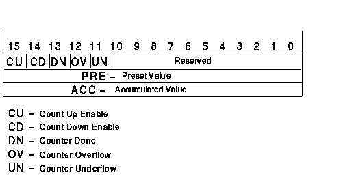
Figure 3-16 PLC-5 Control Structure
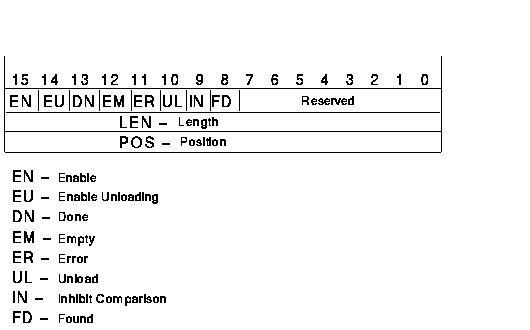
Figure 3-17 PLC-5 SFC Status Structure
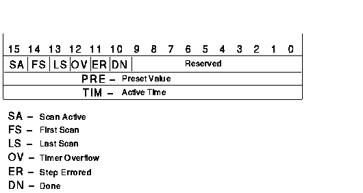
Figure 3-18 PLC-5 Block-Transfer Control Structure
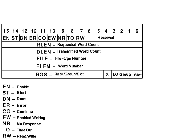
Figure 3-19 PLC-5 Token Data Structure

Figure 3-20 PLC-5 ASCII String Structure

Figure 3-21 PLC-5 PID Control Structure
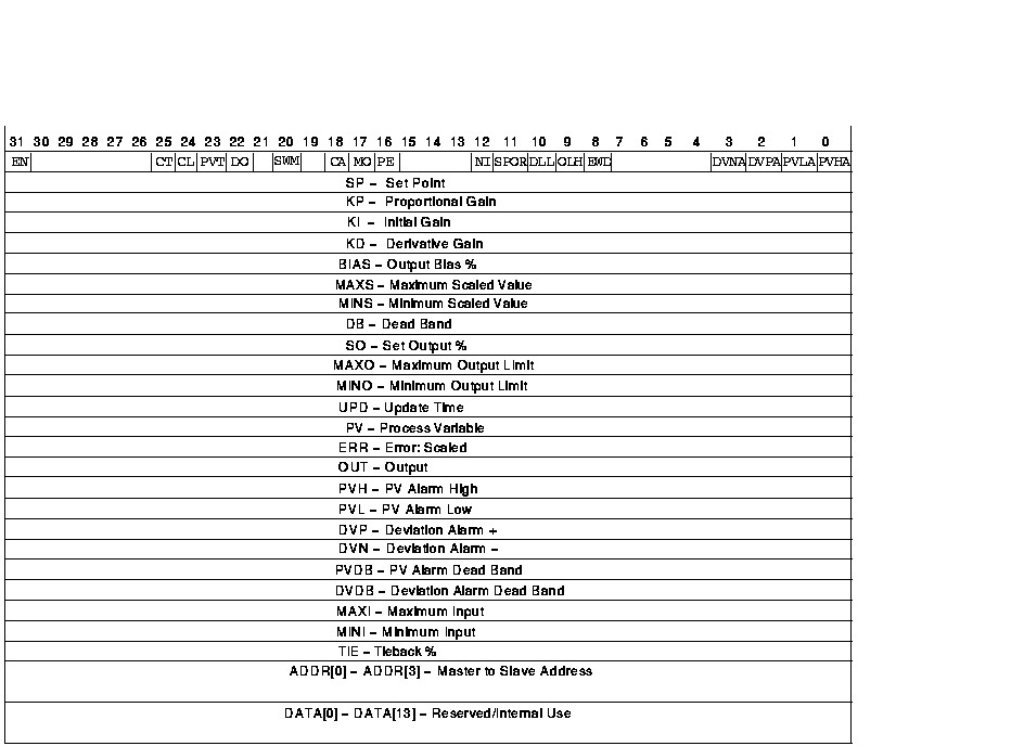
Figure 3-22 PLC-5 Message Control Structure
| Example Address | MMS Type1 | Description |
|---|---|---|
| $T20:0.ACC | UNSIGNED_16 | Timer 0 in file 20 accumulated value |
| C91:3.PRE | INTEGER_16 | Counter 91 in file 3 preset value |
| T:20.CTL/15 | BIT_STRING | Timer 20 in the default timer file (4) Enable bit 2 |
| R6:0.UL | BIT_STRING | Control 0 in file 6 Unload bit 2 |
| T4:20.TD | BIT_STRING | Timer 20 in file 4 Timer Done bit 2 |
| R:1.LEN | INTEGER_16 | Control 1 in the default control file (6) Length value |
| SC10:0.TIM | INTEGER_16 | SFC status 0 in file 10 Active Time value |
| BT11:3.RGS | UNSIGNED_16 | Block Transfer Control 3 in file 11 Rack/Group/Slot |
| TD15:2.HI | INTEGER_16 | Token Data 2 in file 15 High Word value |
| ST16:0.LEN | INTEGER_16 | String 0 in file 16 Length value |
| ST16:2 | VISIBLE_STRING 3 | String 2 in file 16 |
| ST16:3 | OCTET_STRING 3 | String 3 in file 16 |
| PD17:2.DVDB | FLOAT | PID Control 2 in file 17 Deviation Alarm Dead Band |
| PD17:2.EN | BIT_STRING | PID Control 2 in file 17 Enable |
| PD17:1.ADDR[0] | INTEGER_16 | PID Control 1 in file 17 Master-to-slave address 0 |
| MG18:3.RLEN | INTEGER_16 | Message Control 3 in file 18 Requested Length |
| T:5 |
Structure
4
UNSIGNED_16 UNSIGNED_32 UNSIGNED_32 |
All of timer 5 in file 4
Control Preset value Accumulated value |
| R8:10 |
Structure
4
UNSIGNED_16 INTEGER_16 INTEGER_16 |
All of control 10 in file 8
Control Length Position |
| SC9:5 |
Structure
4
INTEGER_16 UNSIGNED_16 UNSIGNED_16 |
All of SFC status 5 in file 9
Control Preset value Active Time |
| BT11:2 |
Structure
4
UNSIGNED_16 INTEGER_16 INTEGER_16 INTEGER_16 INTEGER_16 UNSIGNED_16 |
All of BT 2 in file 11
Control Requested word count Transmitted word count File-type number Word number Rack/Group/Slot |
| TD15:2 |
Structure
4
UNSIGNED_16 UNSIGNED_16 |
All of Token Data 2 in file 15
High Word Low Word |
| PD17:0 |
Structure
4
UNSIGNED_32 FLOAT FLOAT FLOAT FLOAT FLOAT FLOAT FLOAT FLOAT FLOAT FLOAT FLOAT FLOAT FLOAT FLOAT FLOAT FLOAT FLOAT FLOAT FLOAT FLOAT FLOAT FLOAT FLOAT FLOAT Array of 4 UNSIGNED_16 Array of 14 FLOAT |
All of PID Control 0 in file 17
Control Set point Proportional gain Initial gain Derivative gain Output bias % Maximum scaled value Minimum scaled value Dead band Set output % Maximum output limit Minimum output limit Update time Process variable Error:scaled Output PV alarm high PV alarm low Deviation alarm + Deviation alarm - PV alarm dead band Deviation alarm dead band Maximum input Minimum intput Tieback % Master-to-slave address Reserved/internal use |
| MG18:2 |
Structure
4
UNSIGNED_16 INTEGER_16 INTEGER_16 INTEGER_16 Array of 52 INTEGER_16 |
All of Message Control 2 in file 18
Control Error code Requested length Done length Reserved/internal use |
| Previous | Next | Contents | Index |