| Previous | Contents | Index |
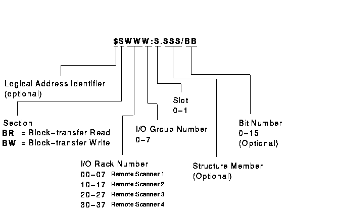
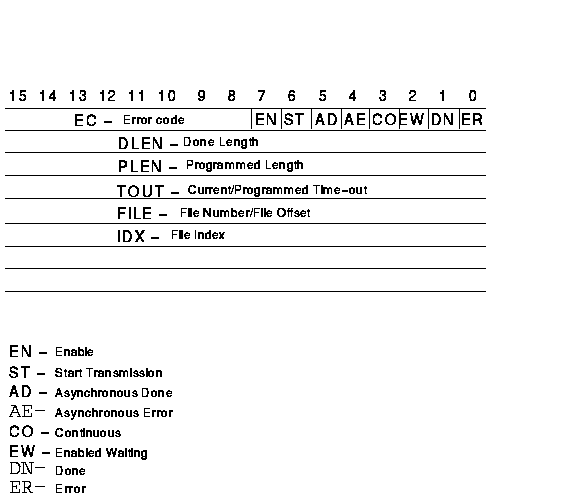
Figure 3-34 shows the structure of a legal Block-Transfer Read/Write Control data table address for the PLC-5/250. Figure 3-35 shows a PLC-5/250 Block-Transfer Read/Write Control structure.
Table 3-22 shows examples of legal Block-Transfer Read/Write Control data table addresses for the PLC-5/250.
Figure 3-34 PLC-5 / 250 Block-Transfer Read / Write Control Address Format

Figure 3-35 PLC-5 / 250 Block-Transfer Read / Write Control Structure

| Example Address | MMS Type1 | Description |
|---|---|---|
| BR01:1.DLEN | UNSIGNED_16 | I/O rack 0, group 1, remote scanner 1, slot 1 done length. |
| BW16:0.PLEN | INTEGER_16 | I/O rack 1, group 6, remote scanner 1, slot 1 programmed length. |
| BR103:1.EN | BIT_STRING 2 | IO rack 10, group 3, remote scanner 2, slot 1 enable bit. |
| $BW27:1 |
Structure
3
UNSIGNED_16 UNSIGNED_16 UNSIGNED_16 UNSIGNED_16 UNSIGNED_16 UNSIGNED_16 UNSIGNED_16 UNSIGNED_16 |
All of Block-Transfer Write Control for I/O
rack 2, group 7, remote scanner 1, slot 1. Error code/status bits. Done/programmed length. Time stamp. Current/programmed time-out. File number/file offset. Reserved. BT directory offset. BT directory length. |
| Previous | Next | Contents | Index |