HP OpenVMS Systems Documentation |
OpenVMS I/O User's Reference Manual
9.14.1 Ethernet Packet FormatThe Ethernet format specifies a two-byte protocol type field followedby an optional length field. The length field is included in transmitpackets and expected in receive packets with the PAD parameter isenabled. The following sections describe these features. Every Ethernet frame has a 2-byte protocol-type field. This field isused to determine the port to which a packet belongs. Protocol typesare independent of addresses; unique protocol designations can beassigned by Xerox Corporation. Whenever an Ethernet user at aparticular station starts an Ethernet port, that user must specify theprotocol type to be used on that port. Messages sent over that portalways have the protocol type attached to them by the device driver,and messages received with that protocol type are delivered to thestarter of that port. Valid protocol types are in the range 05-DDthrough FF-FF. Following are the cross-company protocol types:
Some commonly used protocol types are as follows:
9.14.1.2 Ethernet Packet PaddingThis section describes the PAD parameter NMA$C_PCLI_PAD, which is usedonly in the Ethernet packet format. All CSMA/CD frames must be at least 64 bytes in length. This includesthe Ethernet header, the user data, and the CRC. If the user data, CRC,and Ethernet header together are less than 64 bytes, zero padding bytesare inserted between the user data and the CRC to make a 64-bytepacket. This packet padding cannot be turned off. The PAD parameter directs the LAN drivers to place a data-size field inthe packet between the standard header and the user data. If padding ison (NMA$C_STATE_ON is specified) , a 2-byte length field is insertedafter the Protocol Type field and before the user data. If the PAD parameter is off (NMA$C_STATE_OFF is specified), Ethernetpackets have the following characteristics:
If the PAD parameter is on (NMA$C_STATE_ON is specified), Ethernetpackets have the following characteristics:
9.14.1.3 Protocol Type SharingProtocol types are usually nonshareable; however, an application maybenefit from a shared protocol implementation. The protocol accessparameter (NMA$C_PCLI_ACC) allows a protocol type to be opened ineither of two shareable modes: shared-default (NMA$C_ACC_SHR) andshared-with-destination (NMA$C_ACC_LIM). The LAN drivers also providethe nonshareable exclusive mode (NMA$C_ACC_EXC). (See Table 9-16.)The rules and requirements for using each mode are as follows:
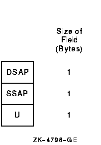
9.14.2 IEEE 802 Packet FormatThe IEEE 802 packet formats accepted for a port depend on the serviceenabled on that port. All 802 packet formats have an 802.2 header. Theservice on the port determines the valid values for the 802.2 fields. When a port is started, the NMA$C_PCLI_SRV parameter in the P2 bufferselects the service on that port. A value of NMA$C_LINSR_CLI specifiesClass I service and a value of NMA$C_LINSR_USR specifies user-suppliedservice (the default). For Class I service, only three packet formats are transmitted andreceived: UI, XID, and TEST. Figure 9-16 shows the 802.2 headerformat for Class I service. Figure 9-16 Class I Service 802.2 Header  The control field for an 802 packet is always an unnumbered controlfield. The unnumbered control field, which is always 1 byte in length,is passed by the P4 argument of the write QIO and can be one of thefollowing binary values:
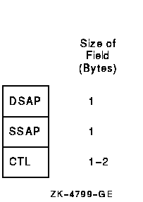
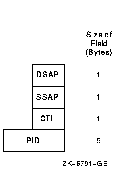
An 802 format port with Class I service is allowed to transmit UI, XID,and TEST commands. An 802 format port with Class I service is allowedto receive UI commands and XID and TEST responses. Refer to the IEEE 802.2 Standard for more information on these controlfield values and response messages. Figure 9-17 shows the 802.2 header format for user-supplied service. Figure 9-17 User-Supplied Service 802.2 Header  The user provides the control field values, which are documented in theIEEE 802.2 Standard. The user-supplied packet format is the genericpacket format as specified in the IEEE 802.2 Standard. Class I packets(see Section 9.14.2.1) are a subset of this generic packet format.Therefore, if the control field value of the user-supplied packet isUI, XID, or TEST, the packet is the same as a Class I packet. Note thatClass II packets, as defined in the IEEE 802.2 Standard, include theUI, XID, and TEST command/response formats. The IEEE 802.2 Standard places restrictions on both user SAPs andsource SAPs (SSAPs). All SAPs are 8 bits long. Figure 9-18 shows theformat of desination SAPs (DSAPs) and SSAPs. Figure 9-18 DSAP and SSAP Format  Definition of the least significant bit depends on whether the SAP is asource SAP (SSAP) or a destination SAP (DSAP). For a DSAP field, theleast significant bit distinguishes group SAPs (bit 0 = 1) fromindividual SAPs (bit 0 = 0). For an SSAP field, the least significantbit distinguishes commands (bit 0 = 0) from responses (bit 0 = 1).Because these two bits are located at the same bit position within theSAP field, a group SAP cannot be used as an SSAP. If this were allowed,a group SAP would be interpreted as an individual SAP with thecommand/response bit set to 1, thus implying a response. The IEEE 802.2Standard reserves for its own definition all SAP addresses with thesecond least significant bit set to 1. You should use these SAP valuesfor their intended purposes, as defined in the IEEE 802.2 Standard. Up to four group SAPs can be enabled on each 802 port. The group SAPsenabled on a controller do not have to be unique for each port; forexample, two 802 format ports can have the same group SAP enabled. Thisallows a single packet coming into the controller to be duplicated andpassed to each port on the controller that has the group SAPenabled---assuming the packet has a DSAP value that is a group SAP. Ifthe received packet has an individual SAP for a DSAP, the packet goesto at most one port. The 802E format uses the 802.2 and 802.1 headers, as shown inFigure 9-19. Figure 9-19 802 Extended Header  For an 802E packet format, the DSAP and SSAP fields are always set tothe SNAP SAP (AA hex). The SNAP SAP value is a special SAP valuereserved for 802 extended format packets. The SNAP SAP valuedistinguishes an 802 packet from an 802 extended packet. The only validcontrol field value for 802 extended packets is UI (unnumberedinformation). On Alpha systems, the 802E format allows user's protocol identifier(PID) sharing. PIDs are usually nonshareable; however, an applicationmay benefit from a shared protocol implementation. The protocol accessparameter (NMA$C_PCLI_ACC) allows a PID to be opened in either of twoshareable modes: shared-default (NMA$C_ACC_SHR) andshared-with-destination (NMA$C_ACC_LIM). The LAN drivers also providethe nonshareable exclusive mode (NMA$C_ACC_EXC). (See Table 9-16.)The rules and requirements for using each mode are as follows:
9.15 LAN Device InformationYou can obtain information on controller characteristics by using theGet Device/Volume Information ($GETDVI) system service. (Refer to theOpenVMS System Services Reference Manual.) $GETDVI returns controller characteristics when you specify the itemcode DVI$_DEVCHAR. Table 9-8 lists these characteristics, which aredefined by the $DEVDEF macro and in the file SYS$LIBRARY:DEVDEF.H.
DVI$_DEVTYPE and DVI$_DEVCLASS return the device type and device classnames, which are defined by the $DCDEF macro and in the fileSYS$LIBRARY:DCDEF.H. The device class name for the LAN Ethernetcontrollers listed in Section 9.2.1 and Section 9.2.2 is alwaysDC$_SCOM. DVI$_DEVBUFSIZ returns the maximum message size. The maximum send orreceive message size depends on the packet format and whether padding(NMA$C_PCLI_PAD) is enabled (see Sections 9.16.1 and9.16.2). DVI$_DEVDEPEND returns the unit and line status bitsand the error summary bits in a longword field as shown inFigure 9-20. Figure 9-20 DVI$_DEVDEPEND Returns  Table 9-9 lists the status values and their meanings. These valuesare defined by the $XMDEF macro. XM$M_STS_ACTIVE is set when the portis started. XM$M_STS_BUFFAIL and XM$M_STS_TIMO are dynamically set andcleared by the LAN driver.
The error summary bits are set when an error occurs. They are read-onlybits. If an error is fatal, the Ethernet port is shut down.Table 9-10 lists the error summary bit values and their meanings.
9.16 LAN Function CodesThe LAN drivers can perform logical, virtual, and physical I/Ooperations. The basic functions are read, write, set mode, setcharacteristics, sense mode, and sense characteristics. Table 9-11lists these functions and their codes. The following sections describethese functions in greater detail.
1V = virtual, L = logical, P = physical (There is nofunctional difference in these operations.) 2The P1 and P3 arguments are only for attention AST QIOs. 3On OpenVMS Alpha, P1, and P5 support 64-bit addresses. 4On OpenVMS Alpha, P1, P4, and P5 support 64-bit addresses. Although the LAN device drivers do not differentiate among logical,virtual, and physical I/O functions (all are treated identically), youmust have the required privilege to issue the request. (Logical I/Ofunctions do not require I/O privilege.)
|
|||||||||||||||||||||||||||||||||||||||||||||||||||||||||||||||||||||||||||||||||||||||||||||||||||||||||||||||||||||||||||||