HP OpenVMS Systems Documentation |
OpenVMS I/O User's Reference Manual
9.9.2 Ethernet Address ClassificationsAn Ethernet address can be a physical address of a single node or amulticast address, depending on the value of the low-order bit of thefirst byte of the address (this bit is transmitted first). Followingare the two types of node addresses:
Contrary to the Ethernet specification and the IEEE 802.3 Standard, thebroadcast address (FF-FF-FF-FF-FF-FF) must be enabled as a multicastaddress in order to receive messages addressed to it. The OpenVMS interface to the LAN controllers allows you to set aphysical address of the controller. The selection of the physicaladdress of a LAN controller is different for CSMA/CD (Ethernet and802.3) and FDDI. For CSMA/CD, all users of the controller must agree on this address. The first user of the controller chooses the physical address; any additional users of the controller must specify either the same physical address, no physical address, or change the address (if allowed). When all channels to the controller are shut down, the next user to start a channel chooses the physical address. The controller's physical address is always chosen on the first successful startup when there are no active ports. If the address is not chosen at this time, the controller's hardware address is used as the physical address. For CSMA/CD, the Can Change Address parameter allows the physicaladdress to be changed even though there are active users. If allcurrent users of the controller have set the NMA$C_PCLI_CCA parameterto NMA$C_STATE_ON, then the physical address can be changed. For FDDI, each port using a controller may specify its own uniquephysical address. Any combination of sharing of physical addresses isalso allowed across the ports of an FDDI controller. For example, portsA, B, and C may use one unique physical address and ports D and E mayuse another unique address. The following are multicast addresses assigned for use in cross-companycommunications:
The following are commonly used multicast addresses:
9.9.5 Token Ring Functional Address MappingExcept for the global broadcast address (FF-FF-FF-FF-FF-FF), Token Ringhardware does not support the 802 standard group LAN address mechanism.Instead, it uses functional addresses. Thesefunctional addresses are locally administered group addresses(multicast addresses). The first two bytes of the address are always03-00 (canonical format), and the remaining four bytes contain a bitmask that specifies which of the 32 possible combination masks is beingdescribed. Because most OpenVMS LAN applications use standard multicast addresses,a mechanism has been designed to map functional addresses to globallyand locally administered multicast addresses. This allows applicationsto use the same multicast addresses that are used in the other LANmedia. Table 9-6 shows the default mapping used by the OpenVMS Alpha TokenRing drivers:
If an application needs to change or add mappings, QIOs exist forperforming such operations. If the system or network manager has arequirement regarding mapping of the functional addresses, the LANcontrol program (LANCP) utility may be used to manage the mapping. Thefollowing example maps the multicast address AB-01-01-01-02-03 tofunctional address 03-00-00-01-00-00 on Token Ring device ICA0:.
Note that it is possible for more than one multicast address to map tothe same functional address. In all cases, the use of the functionaladdress is associated with an individual application's protocol. On Alpha systems, the way to configure an ISA LAN device is to type'isacfg' at the console prompt (>>>). For complete informationon using 'isacfg' from your console prompt, refer to the hardwaredocumentation associated with your system for more information. To help with your configuration, become familiar with the conceptslisted in Table 9-7. Refer to your LAN hardware documentation forconfiguring information on how to set the jumper settings for thosefeatures in Table 9-7.
9.10.1 OpenVMS LAN Devices Requiring ConfigurationThe DE203, DE204, and DE205 Ethernet and DW110 Token Ring devicesrequire configuration using isacfg. The following informationand examples show how this is done. The DE203 is a shared memory Ethernet device. Example 9-1 shows howto configure the OpenVMS software to use the DE203. The followingexample illustrates a configuration of:
The command ("-mk") makes an isacfg entry for an ISA device at slot 1.It is a Single port type of device (-etyp 1). The -handle parametertells the operating system what type of device it is.
9.10.1.2 DW110 Token RingThe DW110 is a bus mastering DMA device on the ISA bus. In addition tosetting up the ISA I/O parameters, you may configure ring speed (4 or16 Mbits) and media (UTP or STP). By using LANCP you can also configurering speed and media during system startup. Example 9-2 shows how toconfigure the OpenVMS software to use the DW110. The following exampleillustrates a configuration of:
The command ("-mk") makes an isacfg entry for an ISA device at slot 4.It is a Single port type of device (-etyp 1). The -handle parametertells the operating system that this is a DW110, that STP media is tobe used, and the ring speed is 16. On Alpha systems prior to OpenVMS Version 7.1, the SYS$EWDRIVER LAN device driver autosensed the media connection: BNC, AUI, or Twisted Pair. LAN adapters supported by this driver include the DE435, DE450, DE500, and Tulip integral Ethernet device. Their device name under OpenVMS is EWx0, where x is the controller letter. With OpenVMS Version 7.1, this driver uses the setting of a console environment variable to select the proper media connection. For each EW device recognized by the console there is a console environment variable called EWx0_MODE, where x is the controller letter (e.g. A, B, C). The console environment variable is set with the command:
In the previous command, the media_selection is one of the following: Twisted-Pair During the OpenVMS device configuration a message is sent to the operator's console that shows which media was set by the console and handed to the device driver. For example, if the EWA0_MODE console environment variable was set to Fast the following message would be broadcast at the console:
If a console environment variable has been set with an unsupported media type for the corresponding device, then the driver attempts to autosense or auto negotiate the media type. Auto negotiation is supported by the DE500-AA. An Alpha system console may assign a controller letter to an adapter differently from OpenVMS. In this case, the letter designation in the message broadcast to the console by the driver may not agree with the console setting. Several different LAN physical layer protocols are supported by OpenVMSwith some differences in frame formats. The following sections describethe similarities and differences in these frame formats. Despitedifferences, the QIO interface to the LAN drivers is designed to allowapplications to run over the different media with few changes to theapplication. The frame formats available in the LAN media are shown in Figure 9-3. Figure 9-3 LAN Frame Formats 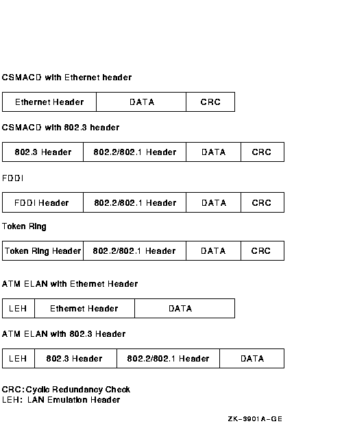 Note that CSMA/CD provides two frame formats and the FDDI provides oneframe format. The 802.1 header is an optional extension to the 802.2header. There are two headers for CSMA/CD frames.
Figure 9-4 illustrates a CSMA/CD frame with an Ethernet header. Figure 9-4 CSMA/CD Frame with Ethernet Header 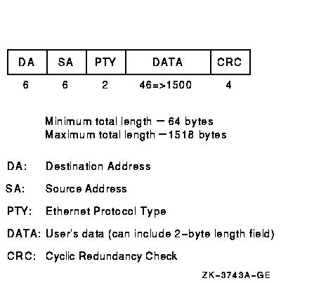 The Ethernet header consists of the DA, SA, and PTY fields. Ethernetframes must be at least 64 bytes in length, which means that theminimum data length is 46 bytes. Applications select Ethernet format byspecifying NMA$C_LINFM_ETH (the default) as the value forNMA$C_PCLI_FMT in their P2 characteristics buffer. If the amount ofactual data to be transmitted is less than 46 bytes, the CSMA/CDdrivers transmit extra bytes of zero after the application data. Figure 9-5 illustrates a CSMA/CD frame with an IEEE 802.3 header. Figure 9-5 CSMA/CD Frame with IEEE 802.3 Header 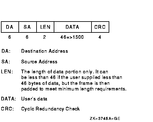 The IEEE 802.3 format is similar to the Ethernet format, except the PTYfield is replaced by the LEN field. Figure 9-6 illustrates the format of FDDI frames. Figure 9-6 FDDI Frame Format 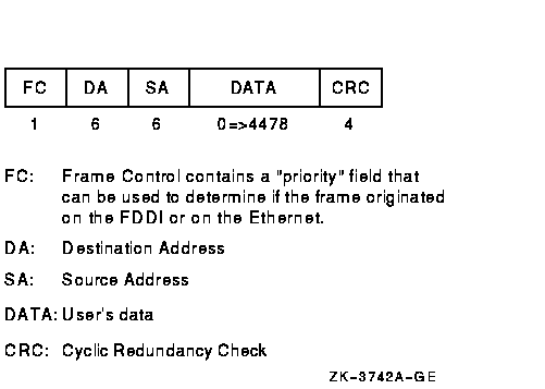 The FDDI header consists of the FC, DA, and SA fields. Figure 9-7 illustrates the format of Token Ring frames. Figure 9-7 Token Ring Frame Format (Alpha Only) 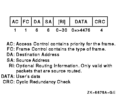 9.12.4 ATM ELAN Frames (Alpha Only)Figure 9-8 illustrates the format of LAN emulation data frame formatfor the IEEE 802.3 and Ethernet Header. Figure 9-8 LAN Emulation Data Frame Format with IEEE802.3/Ethernet Header 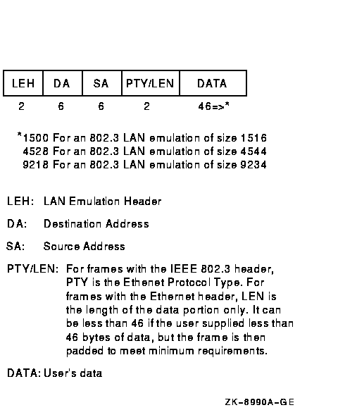 9.12.5 802.2/802.1 HeadersThe 802.2 header follows the 802.3 header in a CSMA/CD frame andfollows the FDDI header in an FDDI frame. The 802.2 header is illustrated in Figure 9-9. Figure 9-9 802.2 Header 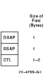 This 802.2 header is followed by the 802.1 header illustrated inFigure 9-10 if the DSAP field is the SNAP SAP (AA hex), the SSAPfield is the SNAP SAP, and the CTL field is UI (03 hex). Figure 9-10 802.1 Header 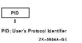 The PID field consists of two subfields: the company portion of the PIDand the implementation-specific portion of the PID (see Figure 9-11). Figure 9-11 802.1 Header Subfields 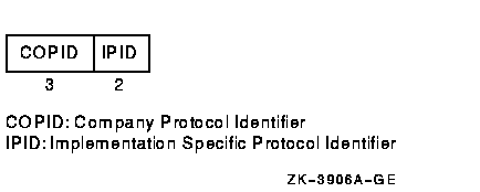 9.12.6 Token Ring Source Routing Header (Alpha Only)Figure 9-12 details the field of the source routing header. Figure 9-12 Source Routing Field (Alpha Only) 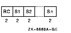 The routing control (RC) contains the information about how the packetis to be routed. The Sn contains the segment identifier for the hop. Each segmentidentifier contains a ring number and bridge number used in the hop. Each port (or user) of a LAN controller either specifies a value forthe format characteristic of the port or assumes the default. Theformat characteristic has three valid values: Ethernet, 802, and 802E.This section describes the actual frame formats for each medium foreach format parameter value. For a format parameter value of NMA$C_LIMFM_ETH (the default), theframe formats are shown in Figure 9-13. Note that a name given to theFDDI frame with the Ethernet format is a mapped Ethernet frame. Figure 9-13 Frames with Ethernet Format 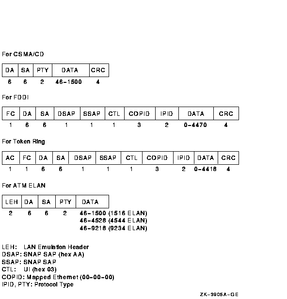 For a format parameter value of NMA$C_PCLI_802, the frame formats areshown in Figure 9-14. Figure 9-14 Frames with 802 Format 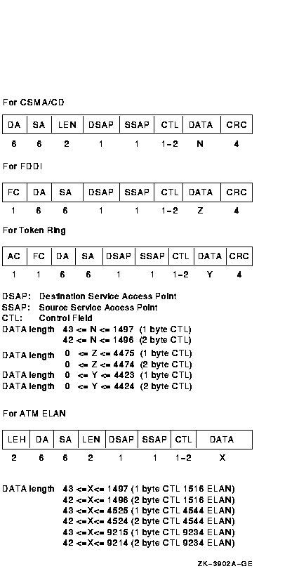 For a format parameter value of NMA$C_PCLI_802E, the frame formats areshown in Figure 9-15. Figure 9-15 Frames with 802E Format 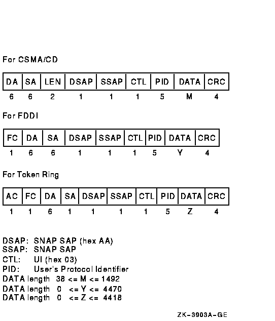 9.14 Features of Packet FormatsThe Ethernet controllers can transmit and receive both Ethernet and802.2/802.3 packets. Each port on a controller is able to transmit andreceive either Ethernet or 802 packets. Ethernet and 802 ports can beassigned on the same controller at the same time. The FDDI controllers can transmit and receive FDDI frames. There is amapped Ethernet frame format that is comparable to the Ethernet packetssent and received by the Ethernet controllers. At the time each port on the controller is started, one of three packetformats can be specified: Ethernet (default), standard 802 (referred toas 802 packet format), and extended 802. If no format is specified, thedefault format is used. Each port on the controller must be unique on that controller. For eachpacket format, there is a parameter that distinguishes the port fromall other ports with the same packet format. For Ethernet packet formatports, the 2-byte protocol type parameter defines the port. For 802packet format ports, the 1-byte SAP defines the port. For extended 802format ports, the 5-byte protocol identifier defines the port. Sections 9.14.1, 9.14.2, and 9.14.3 describe thethree packet formats and the characteristics unique to each format.
|