HP OpenVMS Systems Documentation |
OpenVMS I/O User's Reference Manual
9.2.3 Supported Industry StandardsCSMA/CD drivers support the following features:
FDDI drivers support the following features:
Token Ring drivers support the following features:
ATM drivers over ELAN support the following features:
All LAN drivers support the following features:
Contrary to the IEEE 802.2 Standard, the Global DSAP (FF) must beenabled as a Group SAP to receive messages with the Global DSAP in thedestination SAP field. FDDI conforms to the ANSI Standards defined in the following documents:
9.3 LAN Controller CharacteristicsSystem software and user applications communicate with other systemsthrough the LAN controllers using the QIO interface defined by theOpenVMS LAN driver software. The description of this interface isdescribed later in this chapter. The LAN driver software allowscommunication with these differing technologies in a consistent manner. The LAN controllers implement the Ethernet, FDDI, Token Ring, and ATMspecifications. The Ethernet specification is described in TheEthernet-Data Link Layer and Physical Specification. The FDDIspecifications are available from ANSI. The Token Ring specificationsare available from IEEE. The ATM LAN Emulation specifications areavailable from the ATM Forum. The Classical IP over ATM specification(RFC 1577) is available from the Internet Engineering Task Force (IETF). Ethernet includes Fast Ethernet (802.3u) and Gigabit Ethernet (802.3z).See Section 9.4 and Section 9.5 for more information. Ethernet, FDDI, Token Ring, and ATM networks can be configured to forma single extended LAN using FDDI-Ethernet bridges, FDDI and Ethernetswitches, Token Ring bridges and routers, and ATM switches. This allowsapplications running on a system connected by a LAN controller of onetechnology to communicate with applications running on another systemconnected by a different type of LAN controller. Fast Ethernet (802.3u) is an extension of the IEEE 802.3 standard. Ittypically runs over twisted-pair wiring (100BaseT). It increases thedata transmission rate from 10 to 100Mbps and decreases the maximumlength of a network segment. Fast Ethernet controllers allow either 10or 100Mbps operation for compatibility with existing 10Mbps controllerson the same network segment. The DE500-FA Fast Ethernet controllerprovides a fiber-optic connection (100BaseFX). Table 9-3 shows the types of cabling used for Fast Ethernet.
The OpenVMS operating system supports the following Fast Ethernetadapters on Alpha PCI-based systems: DE500-XA 9.5 Gigabit Ethernet LANs (Alpha Only)Gigabit Ethernet (802.3z) is an extension of the IEEE 802.3 standard.It runs over fiber-optic cabling and twisted-pair wiring. It increasesthe data transmission rate to 1000Mbps. The frame formats are identicalto Ethernet and Fast Ethernet which allows good interoperability acrossthese technologies. Gigabit Ethernet is suitable as a high-speedbackbone interconnect but may be used to connect high-performanceworkstations or systems that need the increased bandwidth. Twisted-pairGigabit controllers allow either 10, 100, or 1000 Mbps operation forcompatibility with existing 10 or 100 Mbps controllers on the samenetwork seqment. Table 9-4 shows the types of cabling used for Gigabit Ethernet.
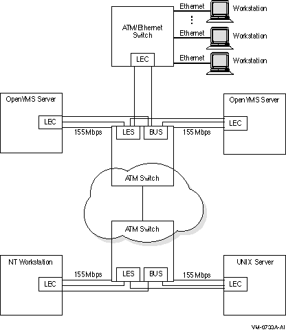
OpenVMS supports the DEGPA Gigabit Ethernet LAN controller on AlphaPCI-based systems. Asynchronous Transfer Mode (ATM) is a cell-oriented switchingtechnology that uses fixed length packets to carry different types ofdata. The ATM protocol communicates by first establishing endpoints betweentwo computers with a virtual circuit (VC) through one or more ATMswitches. ATM then provides a physical path for data flow between theendpoints by either a permanent virtual circuit (PVC), or a switchedvirtual circuit (SVC). Permanent Virtual Circuits (PVCs) Permanent Virtual Circuits are set up and torn down by priorarrangement. They are established manually by a user before the sendingof any data between endpoints on a network. Some PVCs are defineddirectly on the switch; others are predefined for use in managingswitched virtual circuits (SVCs). Switched Virtual Circuits (SVC) Switched virtual circuits require no operator interaction to create andmanage connections between endpoints. Software sets up and tears downconnections dynamically as they are needed through the request of anendpoint. OpenVMS has deployed ATM networks based on the ATM LANE standards andClassical IP over ATM (RFC 1577). The following ATM adapters on Alphasystems are supported by OpenVMS with the ATM LANE standards: DGLTA The following ATM adapters on Alpha systems are supported by OpenVMSwith Classical IP over ATM (RFC 1577): DGLTA 9.6.1 LAN Emulation over an ATM NetworkLAN emulation over an ATM network allows existing applications to runessentially unchanged while also allowing the applications to run oncomputers directly connected to the ATM network. The LAN emulationhides the underlying ATM network at the media access control (MAC)layer, which provides device driver interfaces. Table 9-5 shows the four components that make up a LAN emulationover ATM network. Of the four components, OpenVMS supports only the LANemulation client (LEC).
The LEC exists on all ATM-attached computers that participate in theLAN emulation configuration. LEC provides the ATM MAC-layerconnectionless function that is transparent to the LAN-typeapplications. The LEC, LES, and BUS can exist on one ATM-attachedcomputer or on separate computers. The server functions usually resideinside an ATM switch, but can be implemented on client systems. Figure 9-1 shows the topology of a typical emulated LAN over ATM. Figure 9-1 Emulated LAN Topology  9.6.3 Classical IP Over an ATM NetworkClassical IP (CLIP) implements a data-link level device that has thesame semantics as an Ethernet interface (802.3). This interface is usedby a TCP/IP protocol to transmit 802.3 (IEEE Ethernet) frames over anATM network. The model that OpenVMS Alpha follows for exchanging IPdatagrams over ATM is based on RFC 1577 (Classical IP over ATM). For information on using LANCP commands to manage Classical IP, referto the OpenVMS System Management Utilities Reference Manual: A--L. OpenVMS provides LAN Emulation Client (LEC) support over ATM. The LANEmulation Client software supports IEEE/802.3 Emulated LANs, and UNI3.0 or UNI 3.1 and the following maximum frame size (in bytes): 1516,4544, and 9234. The DAPBA (155 Mb/s) and the DAPCA (622 Mb/s) are ATM adapters forPCI-bus systems that are supported by SYS$HWDRIVER4.EXE. The followingrequirement applies to the DAPBA and DAPCA adapters: Both adapters require a great deal of non-paged pool, and therefore,care should be taken when configuring them. For each DAPBA, Compaqrecommends increasing the SYSGEN parameter NPAGEVIR by 3000000. Foreach DAPCA, Compaq recommends increasing NPAGEVIR by 6000000. To dothis, add the ADD_NPAGEVIR parameter to MODPARAMS.DAT and then runAUTOGEN. For example, add the following command to MODPARAMS.DAT on asystem with two DAPBAs and one DAPCA:
The following restrictions apply to the DAPBA and DAPCA adapters: The adapter cannot be located on a PCI bus that is located behind a PCI-to-PCI bridge. Systems that have this configuration are the following:Digital Personal AlphaWorkstation 600 (MIATA GL) SYS$LAN_ATM4.EXE provides OpenVMS ATM infrastructure for the DAPBA andDAPCA adapters. SYS$ELDRIVER4.EXE provides the Emulated LAN support forthe DAPBA and DAPCA adapters. The DGLPB (155 M/bs) is an ATM device for PCI-bus systems that issupported by SYS$HWDRIVER.EXE. The DGLPA (155 M/bs) is an ATM device for PCI-bus systems that issupported by SY$ATMWORKS351.EXE. The DGLTA (155 M/bs) is an ATM device for Turbochannel systems with theexception of the DEC 3000-300 that is supported by SYS$HCDRIVER.EXE. SYS$LAN_ATM.EXE provides the OpenVMS ATM infrastructure for the DGLPB,DGLPA, and DGLTA adapters. SYS$ELDRIVER.EXE provides the Emulated LANsupport for the DGLPB, DGLPA, and DGLTA adapters. The Emulated LAN driver provides the means for communicating over theLAN ATM. The device type for the Emulated LAN device is DT$_EL_ELAN. The device name for the Emulated LAN is:
9.7.1 Specifying the User to Network Interface (UNI)The ATM software is set to autosense the UNI version by default.Setting bit 3 of the system parameter, LAN_FLAGS, to 1 enables UNI 3.0over all ATM adapters. Setting bit 4 of the system parameter,LAN_FLAGS, to 1 enables UNI 3.1 over all ATM adapters. The ATM drivers have the capability of operating with eithersynchronous optical network (SONET) or synchronous digital hierarchy(SDH) framing. Setting bit 0 of the system parameter, LAN_FLAGS, to 1enables SDH framing. Setting bit 0 of the system parameter, LAN_FLAGS,to 0 enables SONET framing (default). For this to take affect, thesystem parameter must be specified correctly before the ATM adapterdriver is loaded. OpenVMS Alpha does not support ATM adapters as boot devices. The LANCP utility sets up an Emulated LAN (ELAN). If the ELAN isdefined in the permanent database, these settings take affect at boottime. To define the commands in the permanent database for specificadapters, you invoke the DEFINE DEVICE commands. Once these commandsdefine the adapters in the permanent database, the ELAN can be startedduring system startup. You can also invoke the LANCP SET commands to start up an ELAN afterthe system is booted. The following example shows the DEFINE DEVICE commands that define theadapter in the permanent database.
The following example shows the SET DEVICE commands required forsetting up an ELAN with the desired parameters. Note that some of thecommands generate a console message.
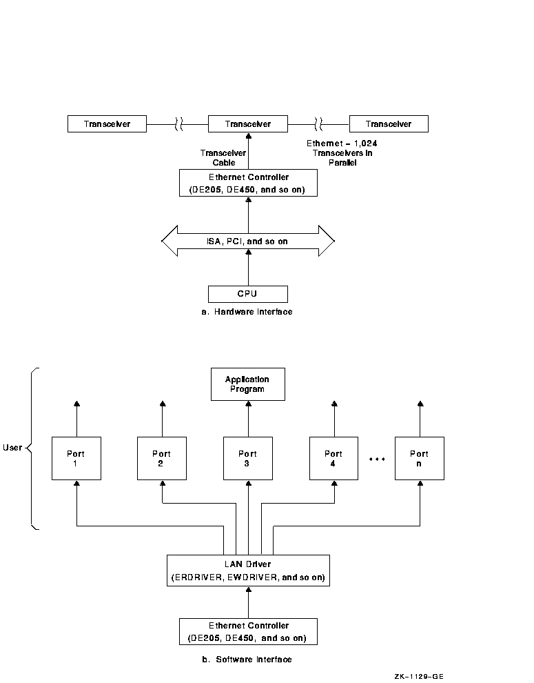
For information about using LANCP and system manager commands withqualifiers for LAN emulation over ATM networks, refer to theOpenVMS System Management Utilities Reference Manual: A--L, and OpenVMS System Manager's Manual. A port in a LAN configuration consists of a protocoltype, a service access point (SAP) or protocol identifier, and acontroller. There are as many ports on a LAN controller as there areprotocol types, SAPs, and protocol identifiers. Each port isindependent of other ports running on the same LAN controller. Application programs use either the LAN driver's QIO interface or VCI interface to perform I/O operations to and from other nodes on the LAN. This chapter describes the QIO interface. Figure 9-2 shows the relationship of most Ethernet controllers to the processor and to the user application program. Figure 9-2 Typical Ethernet Configuration  9.8.1 Driver Initialization and OperationThe following sequence initializes and starts a port on a LAN devicedriver:
The sample programs described in Section 9.18.2 illustrate how to perform these procedures for Ethernet and IEEE 802 ports. The LAN is a medium for creating a network; it is not a network byitself. The LAN controller and the local system constitute a node.Nodes on the LAN are identified by unique Ethernet addresses. A messagecan be sent to one, several, or all nodes on the LAN simultaneously,depending on the Ethernet address used. You do not have to specify theEthernet address of your own node to communicate with other nodes onthe same Ethernet. However, you do need to know the Ethernet address ofthe node with which you want to communicate. An Ethernet address is 48 bits in length. Ethernet addresses arerepresented by the Ethernet standard as six pairs of hexadecimal digits(six bytes), separated by hyphens (for example, AA-01-23-45-67-FF). Thebytes are displayed from left to right in the order in which they aretransmitted; bits within each byte are transmitted from right to left.In this example, byte AA is transmitted first; byte FF is transmittedlast. (See the description of NMA$C_PCLI_PHA in Table 9-16,Section 9.16.3.1, for the internal representation of addresses.) Upon application, IEEE assigns a block of addresses to a producer ofLAN nodes. Thus, every manufacturer has a unique set of addresses touse. Normally, one address out of the assigned block of physicaladdresses is permanently associated with each controller (usually inread-only memory). This address is known as the hardware address of thecontroller. Each individual controller has a unique hardware address.
|