 |
HP OpenVMS Programming Concepts Manual
9.8.2 Signal Argument Vector
Signaling a condition value causes systems to pass control to a special
subprogram called a condition handler. The operating system invokes a
default condition handler unless you have established your own. The
default condition handler displays the associated error message and
continues or, if the error is a severe error, terminates program
execution.
The signal argument vector contains information describing the nature
of the hardware or software condition. Figure 9-6 illustrates the
open-ended structure of the signal argument vector, which can be from 3
to 257 longwords in length.
The format of the signal argument array and the data it returns is the
same on VAX systems, Alpha systems, and I64 systems with the exception
of the processor status (PS) returned on Alpha systems and I64 and the
processor status longword (PSL) returned on VAX systems. On Alpha and
I64 systems, it is the low-order 32 bits of the PS. Note that the PS in
the signal arrays on I64 systems is fabricated.
On Alpha systems, CHF$IS_SIG_ARGS and CHF$IS_SIG_NAME are aliases for
CHF$L_SIG_ARGS and CHF$L_SIG_NAME, as shown in Figure 9-6, and the
PSL field for VAX systems is the processor status (PS) field for Alpha
systems.
Figure 9-6 Format of the Signal Argument Vector
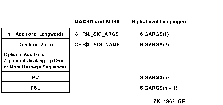
Fields of the Signal Argument Vector
SIGARGS(1)
An unsigned integer (n) designating the number of longwords
that follow in the vector, not counting the first, including PC and
PSL. (On Alpha systems, the value used for the PSL is the low-order
half of the Alpha processor status [PS] register. For I64 systems the
PS is also used, but the PS is fabricated.) For example, the first
entry of a 4-longword vector would contain a 3.
SIGARGS(2)
This argument is a 32-bit value that uniquely identifies a hardware or
software exception condition. The format of the condition code, which
is the same for VAX systems, Alpha systems, and I64 systems, is shown
and described in Figure 9-3. However, Alpha systems do not support
every condition returned on VAX systems, and Alpha systems define
several new conditions that cannot be returned on VAX systems. Some
Alpha conditions exist on I64, some Alpha conditions are not
appropriate for I64 and there are some new I64 conditions.
Table 9-3 lists VAX system condition codes that cannot be returned
on Alpha and I64 systems.
If more than one message is associated with the error, this is the
condition value of the first message. Handlers should always check
whether the condition is the one that they expect by examining the
STS$V_COND_ID field of the condition value (bits <27:3>). Bits
<2:0> are the severity field. Bits <31:28> are control
bits; they may have been changed by an intervening handler and so
should not be included in the comparison. You can use the RTL routine
LIB$MATCH_COND to match the correct fields. If the condition is not
expected, the handler should resignal by returning false (bit <0>
= 0). The possible exception conditions and their symbolic definitions
are listed in Table 9-1.
SIGARGS(3 to n --1)
Optional arguments that provide additional information about the
condition. These arguments consist of one or more message sequences.
The format of the message description varies depending on the type of
message being signaled. For more information, see the SYS$PUTMSG
description in the HP OpenVMS System Services Reference Manual. The format of a message sequence is
described in Section 9.11.
SIGARGS(n)
The program counter (PC) of the next instruction to be executed if any
handler (including the system-supplied handlers) returns with the
status SS$_CONTINUE. For hardware faults, the PC is that of the
instruction that caused the fault. For hardware traps, the PC is that
of the instruction following the one that caused the trap. The error
generated by LIB$SIGNAL is a trap. For conditions signaled by calling
LIB$SIGNAL or LIB$STOP, the PC is the location following the CALLS or
CALLG instruction. See the VAX Architecture Reference Manual, Alpha Architecture Reference Manual, or the
Intel® Itanium® Architecture Software Developer's
Manual for a detailed description of faults and traps.
SIGARGS(n+1)
On VAX systems the processor status longword (PSL), or on Alpha and I64
systems the processor status (PS) register (which is fabricated on
I64), of the program at the time that the condition was signaled.
For information about the PSL on VAX systems, and the PS on Alpha
systems, see the VAX Architecture Reference Manual and the Alpha Architecture Reference Manual.
Note
LIB$SIGNAL and LIB$STOP copy the variable-length argument list passed
by the caller. Then, before calling a condition handler, they append
the PC and PSL (or on Alpha and I64 systems the processor status (PS)
register, which is fabricatred on I64) entries to the end of the list.
|
The formats for some conditions signaled by the operating system and
the run-time library are shown in Figure 9-7 and Figure 9-8.
These formats are the same on VAX systems and Alpha systems, except for
the PSL, or on Alpha and I64 systems, the PS register (which is
fabricated on I64).
Figure 9-7 Signal Argument Vector for the Reserved Operand
Error Conditions
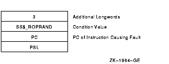
Figure 9-8 Signal Argument Vector for RTL Mathematics Routine
Errors
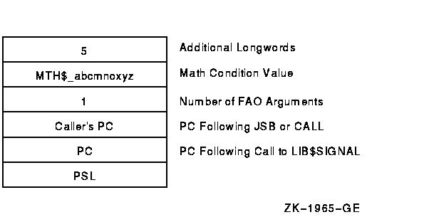
The caller's PC is the PC following the calling program's JSB or CALL
to the mathematics routine that detected the error. The PC is that
following the call to LIB$SIGNAL.
9.8.3 VAX Mechanism Argument Vector (VAX Only)
On VAX systems, the mechanism argument vector is a 5-longword vector
that contains all of the information describing the state of the
process at the time of the hardware or software signaled condition.
Figure 9-9 illustrates a mechanism argument vector for VAX systems.
Figure 9-9 Format of a VAX Mechanism Argument Vector
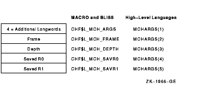
Fields of the VAX Mechanism Argument Vector
MCHARGS(1)
An unsigned integer indicating the number of longwords that follow, not
counting the first, in the vector. Currently, this number is always 4.
MCHARGS(2)
The address of the stack frame of the routine that established the
handler being called. You can use this address as a base from which to
reference the local stack-allocated storage of the establisher, as long
as the restrictions on the handler's use of storage are observed. For
example, if the call stack is as shown in Figure 9-4, this argument
points to the call frame for procedure A.
You can use this value to display local variables in the procedure that
established the condition handler if the variables are at known offsets
from the frame pointer (FP) of the procedure.
MCHARGS(3)
The stack depth, which is the number of stack frames between the
establisher of the condition handler and the frame in which the
condition was signaled. To ensure that calls to LIB$SIGNAL and LIB$STOP
appear as similar as possible to hardware exception conditions, the
call to LIB$SIGNAL or LIB$STOP is not included in the depth.
If the routine that contained the hardware exception condition or that
called LIB$SIGNAL or LIB$STOP also handled the exception condition,
then the depth is zero; if the exception condition occurred in a called
routine and its caller handled the exception condition, then the depth
is 1. If a system service signals an exception condition, a handler
established by the immediate caller is also entered with a depth of 1.
The following table shows the stack depths for the establishers of
condition handlers:
| Depth |
Meaning |
|
--3
|
Condition handler was established in the last-chance exception vector.
|
|
--2
|
Condition handler was established in the primary exception vector.
|
|
--1
|
Condition handler was established in the secondary exception vector.
|
|
0
|
Condition handler was established by the frame that was active when the
exception occurred.
|
|
1
|
Condition handler was established by the caller of the frame that was
active when the exception occurred.
|
|
2
|
Condition handler was established by the caller of the caller of the
frame that was active when the exception occurred.
|
|
.
|
|
|
.
|
|
|
.
|
|
For example, if the call stack is as shown in Figure 9-4, the depth
argument passed to handler A would have a value of 2.
The condition handler can use this argument to determine whether to
handle the condition. For example, the handler might not want to handle
the condition if the exception that caused the condition did not occur
in the establisher frame.
MCHARGS(4) and MCHARGS(5)
Copies of the contents of registers R0 and R1 at the time of the
exception condition or the call to LIB$SIGNAL or LIB$STOP. When
execution continues or a stack unwind occurs, these values are restored
to R0 and R1. Thus, a handler can modify these values to change the
function value returned to a caller.
9.8.4 Alpha Mechanism Argument Vector (Alpha Only)
On Alpha systems, the mechanism array returns much the same data as it
does on VAX systems, though its format is changed. The mechanism array
returned on Alpha systems preserves the contents of a larger set of
integer scratch registers as well as the Alpha floating-point scratch
registers. In addition, because Alpha registers are 64 bits long, the
mechanism array is constructed of quadwords (64 bits), not longwords
(32 bits) as it is on VAX systems. Figure 9-10 shows the format of
the mechanism array on Alpha systems.
Figure 9-10 Mechanism Array on Alpha Systems

Table 9-12 describes the arguments in the mechanism array.
Table 9-12 Fields in the Alpha Mechanism Array
| Argument |
Description |
|
CHF$IS_MCH_ARGS
|
Represents the number of quadwords in the mechanism array, not counting
the argument count quadword. (The value contained in this argument is
always 43.)
|
|
CHF$IS_MCH_FLAGS
|
Flag bits <63:0> for related argument mechanism information
defined as follows for CHF$V_FPREGS:
Bit <0>: When set, the process has already performed a
floating-point operation and the floating-point registers stored in
this structure are valid.
If this bit is clear, the process has not yet performed any
floating-point operations, and the values in the floating-point
register slots in this structure are unpredictable.
|
|
CHF$PH_MCH_FRAME
|
The frame pointer (FP) in the procedure context of the establisher.
|
|
CHF$IS_MCH_DEPTH
|
Positive count of the number of procedure activation stack frames
between the frame in which the exception occurred and the frame depth
that established the handler being called.
|
|
CHF$PS_MCH_DADDR
|
Address of the handler data quadword if the exception handler data
field is present (as indicated by PDSC.FLAGS.HANDLER_DATA_VALID);
otherwise, contains zero.
|
|
CHF$PH_MCH_ESF_ADDR
|
Address of the exception stack frame (see the Alpha Architecture Reference Manual).
|
|
CHF$PH_MCH_SIG_ADDR
|
Address of the signal array. The signal array is a 32-bit (longword)
array.
|
|
CHF$IH_MCH_SAVR
nn
|
A copy of the saved integer registers at the time of the exception. The
following registers are saved: R0, R1, and R16--R28. Registers R2--R15
are implicitly saved in the call chain.
|
|
CHF$FM_MCH_SAVF
nn
|
A copy of the saved floating-point registers at the time of the
exception or may have unpredictable data as described in
CHF$IS_MCH_FLAGS. If the floating-point register fields are valid, the
following registers are saved: F0, F1, and F10--F30. Registers F2--F9
are implicitly saved in the call chain.
|
For more information and recommendations about using the mechanism
argument vector on Alpha systems, see Migrating to an OpenVMS AXP System: Recompiling and Relinking Applications. Note that this
manual has been archived but is available on the OpenVMS Documentation
CD-ROM.
9.8.5 I64 Mechanism Vector Format
On I64 systems, the 64-bit-wide mechanism array is the argument
mechanism in the handler call. The array is shown in Figure 9-11.
The CHF$IH_MCH_RETVAL and CHF$FH_MCH_RETVAL2 quadwords save the state
of registers R8 and R9 at the time of the call to LIB$SIGNAL or
LIB$STOP. The CHF$FH_MCH_RETVAL_FLOAT, CHF$FH_MCH_RETVAL2_FLOAT, and
CHF$FH_MCH_SAVFnn octawords save the state of the
floating-point registers at the time of the call to LIB$SIGNAL or
LIB$STOP. If not modified by a handler during CHF processing (as
described below), these values will become the values of those
registers after completion of CHF processing (either by continuation or
by unwinding).
The only supported method for modifying return values in a procedure's
invocation context (CHF$IH_MCH_RETVAL, CHF$IH_MCH_RETVAL2,
CHF$FH_MCH_RETVAL_FLOAT, CHF$FH_MCH_RETVAL2_FLOAT) is by using routine
SYS$SET_RETURN_VALUE. The only supported method for modifying all other
registers in a procedure invocation context is by using routine
LIB$I64_PUT_INVO_REGISTERS, as described in the HP OpenVMS Calling Standard.
Figure 9-11 I64 Mechanism Vector Format
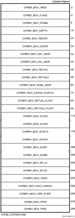
Table 9-13 Contents of the I64 Argument Mechanism Array (MECH)
| Field Name |
Contents |
|
CHF$IS_MCH_ARGS
|
Count of quadwords in this array starting from the next quadword,
CHF$PH_MCH_FRAME (not counting the first quadword that contains this
longword). This value is 71 if CHF$V_FPREGS_VALID is clear, and 263 if
CHF$V_FPREGS_VALID is set.
|
|
CHF$IS_MCH_FLAGS
|
Flag bits <31:0> for related argument-mechanism information
defined as follows:
|
CHF$V_FREGS_VALID
|
Bit 0. When set, the process has already performed a floating-point
operation in registers F2-F31 and the contents of the CHF$FH_MCH_SAVF
nn fields of this structure are valid.
When this bit is clear, the contents of the CHF$FH_MCH_SAVF
nn fields are undefined.
|
|
CHF$V_FPREGS2_VALID
|
Bit 1. When set, the process has already performed a floating-point
operation in registers F32-F127 and the floating-point registers stored
in the extension to this structure are valid.
If this bit is clear, the process has not yet performed any
floating-point operations in registers F32-F127, and the pointer to the
extension area (CHF$FH_MCH_SAVF32_SAVF127) will be zero.
|
|
|
CHF$PH_MCH_FRAME
|
Contains the previous stack pointer, or PSP (the value of the SP at
procedure entry) for the procedure context of the establisher, as
described in HP OpenVMS Calling Standard.
|
|
CHF$IS_MCH_DEPTH
|
Positive count of the number of procedure activation stack frames
between the frame in which the exception occurred and the frame depth
that established the handler being called, as described in the
HP OpenVMS Calling Standard.
|
|
CHF$IS_MCH_RESVD1
|
Reserved to HP.
|
|
CHF$PH_MCH_DADDR
|
Address of the handler data quadword (start of the Language Specific
Data area, LSDA, see the HP OpenVMS Calling Standard) if the exception-handler data
field is present in the unwind information block (as indicated by
OSSD$V_HANDLER_DATA_VALID); otherwise, contains 0.
|
|
CHF$PH_MCH_ESF_ADDR
|
Address of the exception stack frame.
|
|
CHF$PH_MCH_SIG_ADDR
|
Address of the 32-bit form of signal array. This array is a 32-bit wide
(longword) array. This is the same array that is passed to a handler as
the signal argument vector.
|
|
CHF$IS_MCH_RETVAL
|
Contains a copy of R8 at the time of the exception.
|
|
CHF$IS_MCH_RETVAL2
|
Contains a copy of R9 at the time of the exception.
|
|
CHF$PH_MCH_SIG64_ADDR
|
Address of the 64-bit form of signal array. This array is a 64-bit wide
(quadword) array.
|
|
CHF$FH_MCH_SAVF32_SAVF127
|
Address of the extension to the mechanism array that contains copies of
F32-F127 at the time of the exception.
|
|
CHF$IS_MCH_RETVAL_FLOAT
|
Contains a copy of F8 at the time of the exception.
|
|
CHF$IS_MCH_RETVAL2_FLOAT
|
Contains a copy of F9 at the time of the exception.
|
|
CHF$FH_MCH_SAVF
nn
|
Contain copies of floating-point registers F2-F5 and F12-F31. Registers
F6-F7 and F10-F11 are implicitly saved in the exception frame.
|
|
CHF$FH_MCH_SAVB
nn
|
Contains copies of branch registers B1-B5 at the time of the exception.
|
|
CHF$FH_MCH_AR_LC
|
Contains a copy of the Loop Count Register (AR65) at the time of the
exception.
|
|
CHF$FH_MCH_AR_EC
|
Contains a copy of the Epilog Count Register (AR66) at the time of the
exception.
|
|
CHF$PH_MCH_OSSD
|
Address of the operating system-specific data area.
|
|
CHF$PH_MCH_INVO_HANDLE
|
Contains the invocation handle of the procedure context of the
establisher (See the HP OpenVMS Calling Standard.)
|
|
CHF$PH_MCH_UWR_START
|
Address of the unwind region.
|
9.8.6 Multiple Active Signals
A signal is said to be active until the routine that signaled regains
control or until the stack is unwound or the image exits. A second
signal can occur while a condition handler or a routine it has called
is executing. This situation is called multiple active
signals or multiple exception conditions.
When this situation occurs, the stack scan is not performed in the
usual way. Instead, the frames that were searched while processing all
of the previous exception conditions are skipped when the current
exception condition is processed. This is done in order to avoid
recursively reentering a routine that is not reentrant. For example,
Fortran code typically is not recursively reentrant. If a Fortran
handler were called while another activation of that handler was still
going, the results would be unpredictable.
A second exception may occur while a condition handler or a procedure
that it has called is still executing. In this case, when the exception
dispatcher searches for a condition handler, it skips the frames that
were searched to locate the first handler.
The search for a second handler terminates in the same manner as the
initial search, as described in Section 9.6.
If the SYS$UNWIND system service is issued by the second active
condition handler, the depth of the unwind is determined according to
the same rules followed in the exception dispatcher's search of the
stack: all frames that were searched for the first condition handler
are skipped.
Primary and secondary vectored handlers, on the other hand, are always
entered when an exception occurs.
If an exception occurs during the execution of a handler that was
established in the primary or secondary exception vector, that handler
must handle the additional condition. Failure to do so correctly might
result in a recursive exception loop in which the vectored handler is
repeatedly called until the user stack is exhausted.
The modified search routine is best illustrated with an example. Assume
the following calling sequence:
- Routine A calls routine B, which calls routine C.
- Routine C signals an exception condition (signal S), and the
handler for routine C (CH) resignals.
- Control passes to BH, the handler for routine B. The call frame for
handler BH is located on top of the signal and mechanism arrays for
signal S. The saved frame pointer in the call frame for BH points to
the frame for routine C.
- BH calls routine X; routine X calls routine Y.
- Routine Y signals a second exception condition (signal T).
Figure 9-12 illustrates the stack contents after the second exception
condition is signaled.
Figure 9-12 Stack After Second Exception Condition Is
Signaled
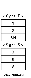
Normally, the OpenVMS Condition Handling facility (CHF) searches
all currently active frames for condition handlers, including B and C.
If this happens, however, BH is called again. At this point, you skip
the condition handlers that have already been called. Thus, the search
for condition handlers should proceed in the following order:
YH
XH
BHH (the handler for routine B's handler)
AH
- The search now continues in its usual fashion. The CHF examines the
primary and secondary exception vectors, then frames Y, X, and BH.
Thus, handlers YH, XH, and BHH are called. Assume that these handlers
resignal.
- The CHF now skips the frames that have already been searched and
resumes the search for condition handlers in routine A's frame. The
depths that are passed to handlers as a result of this modified search
are 0 for YH, 1 for XH, 2 for BHH, and 3 for AH.
Because of the possibility of multiple active signals, you should be
careful if you use an exception vector to establish a condition
handler. Vectored handlers are called, not skipped, each time an
exception occurs.
|


