| Previous | Contents | Index |
When applications are deployed, often the frontend is separated from the backend and router, as shown in Figure 1-10.
Figure 1-10 RTR Deployed on Two Nodes

In this example, the frontend with the client application resides on one node, and the router with the server application reside a node that has both the router and backend roles. This is a typical configuration where routers are placed on backends rather than on frontends. A further separation of workload onto three nodes is shown in Figure 1-11. However, in this configuration, there remain several single points of failure where one node/role or a network outage can disrupt processing of transactions.
Figure 1-11 RTR Deployed on Three Nodes

While this three-node configuration separates transaction load onto three nodes, it does not provide for continuing work if one of the nodes fails or becomes disconnected from the others. In many applications, there is a need to ensure that there is a server always available to access the database.
Standby server
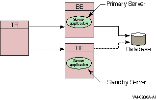
In this case, a standby server will do the job. A standby server (see Figure 1-12) is a process or application that can take over when the primary server is not available, due to hardware failure, application software failure or network outage.
Both the primary and the standby server have the capability to access the same database, but the primary processes all transactions unless it is unavailable. On the other hand, the standby processes transactions only when the primary becomes unavailable. When not being used to process transactions, the standby CPU can do other work.
The standby server is usually placed on a node other than the node where the primary server runs, and should be, to avoid being a single point of failure. Network capability, clustering or disk-sharing technology, and appropriate software must be available on both primary and standby backend systems when running RTR.
Figure 1-12 Standby Server Configuration
Shadow Server and Transactional shadowing
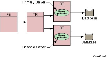
To increase transaction processing availability, transactions can be shadowed with a shadow server, as shown in Figure 1-13. The system where the shadow server runs can be made available with clustering technology. A shadow server eliminates the single point of failure that is evident in Figure 1-12. In a shadow configuration, the second database of Figure 1-13 is available even when the first is not.
Use of a shadow server is called transactional shadowing and is accomplished by having a second location, often at a different site, where transactions are also recorded. Data are recorded in two separate data stores or databases. The router knows about both backends and sends all transactions to both backends. RTR provides the server application with the necessary information to keep the two databases synchronized.
Figure 1-13 Transactional Shadowing Configuration
RTR Journal
In the RTR environment, one data store (database or data file) is elected the primary, and a second data store is made the shadow. The shadow data store is a copy of the data store kept on the primary. If either data store becomes unavailable, all transactions continue to be processed and stored on the surviving data store. At the same time, RTR makes a record of (remembers) all transactions stored only on the shadow data store in the RTR journal by the shadow server.
When creating the configuration used by an application and defining the nodes where a facility has its frontends, routers, and backends, the setup must also define which nodes will have journal files. Each backend in an RTR configuration must have a journal file to capture transactions when other nodes are unavailable. When the primary server and data store become available again, RTR replays the transactions in the journal to the primary data store through the primary server. This brings the data store back into synchronization.
With transactional shadowing, there is no requirement that hardware, the data store, or the operating system at different sites be the same. You could, for example, have one site running OpenVMS and another running Windows NT; the RTR transactional commit process would be the same at each site. Because the database resides at both sites, either backend can have an outage and all transactions will still be processed and recovered.
Transactional shadowing shadows only transactions controlled by RTR. |
For full redundancy to assure maximum availability, a configuration could employ disk shadowing in clusters at separate sites coupled with transactional shadowing across sites. Disk shadowing used in specific cluster environments copies data to another disk to ensure data availability. Transactional shadowing copies only transactional data.
Additionally, an RTR configuration typically deploys multiple frontends running client applications with connections to several routers to ensure continuing operation if a particular router fails.
In the RTR environment, in addition to the placement of frontends, routers, and servers, the application designer must determine what server capabilities to use. RTR provides four types of software servers for application use:
These are described in the next few paragraphs. You specify server types to your application in RTR API calls.
RTR server types help to provide continuous availability and a secure transactional environment.
Standby server
The standby server remains idle while the RTR primary backend server performs its work, accepting transactions and updating the database. When the primary server fails, the standby server takes over, recovers any in-progress transactions, updates the database, and communicates with clients until the primary server returns. There can be many instances of a standby server. Activation of the standby server is transparent to the user.
A typical standby configuration is shown in Figure 1-12, Standby Server Configuration. Both physical servers running the RTR backend software are assumed by RTR to connect to the same database. The primary server is typically in use, and the standby server can be either idle or used for other applications, or data partitions, or facilities. When the primary server becomes unavailable, the standby server takes over and completes transactions as shown by the dashed line. Primary server failure could be caused by server process failure or backend (node) failure.
Standby in a cluster
The intended and most common use of a standby server is in a recognized cluster environment. In a noncluster or unrecognized cluster environment, seamless failover of standbys is not guaranteed. For RTR, clusters supported by OpenVMS and Tru64 UNIX are recognized clusters, whose processing is controlled by a lock manager. Windows and Sun clusters can use disk-sharing, unrecognized cluster technology.
Standby servers are "spare" servers that automatically take over from the main backend if it fails. This takeover is transparent to the application.
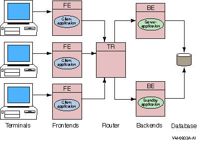
Figure 1-14 shows a simple standby configuration. The two backend nodes are members of a cluster environment, and are both able to access the database.
For any one key range, the main or primary server (Server application) runs on one node while the standby server (Standby application) runs on the other node. The standby server process is running, but RTR does not pass any transactions to it. Should the primary node fail, RTR starts passing transactions to the Standby application.
Note that one node can contain the primary servers for one key range and standby servers for another key range to balance the load across systems. This allows the nodes in a cluster environment to act as standby for other nodes without having idle hardware. When setting up a standby server, both servers must have access to the same journal.
Figure 1-14 Standby Servers
Transactional shadow server
The transactional shadow server places all transactions recorded on the primary server on a second database. The transactional shadow server can be at the same site or at a different site, with networking capability available.
When one member of a shadow set fails, RTR remembers the transactions executed at the surviving site in a journal, and replays them when the failed site returns. Only after all journaled transactions are recovered does the recovering site fully process new online transactions. During recovery, new transactions are processed at the surviving site and added to the journal for the recovering site.
Transactional shadowing is done by partition. A transactional shadow configuration can have only two members of the shadow set.
Shadow servers are servers on separate backends that handle the same transactions in parallel on identical copies of the database.
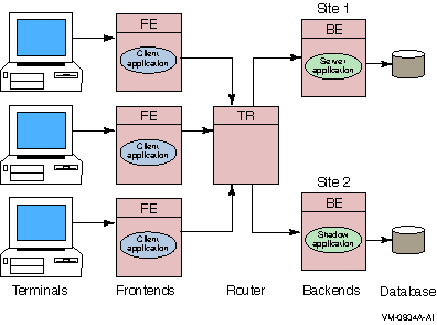
Figure 1-15 shows a simple shadow configuration. The main backend server application at Site 1 and the shadow server (Shadow application) at Site 2 both receive every transaction for the data partition they are servicing. Should Site 1 fail, Site 2 continues to operate without interruption. Sites can be geographically remote, for example, available at separate locations in a wide area network (WAN).
Figure 1-15 Shadow Servers
Concurrent server
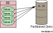
The concurrent server is an additional instance of a server application running on the same node. RTR delivers transactions to a free server from the pool of concurrent servers. If one server fails, the transaction in process is replayed to another server in the concurrent pool. Concurrent servers are designed primarily to increase throughput and can exploit Symmetric Multiprocessing (SMP) systems. Figure 1-16, Concurrent Servers, illustrates the use of concurrent servers sending transactions to the same partition on a backend, the partition A-N.
Concurrent servers allow transactions to be processed in parallel to increase throughput. Concurrent servers deal with the same database partition, and may be implemented as multiple channels within a single process or as one channel in separate processes. The application designer must determine if transactions can be processed concurrently by the database or server application. Deadlocks can occur if every transaction competes for the same database lock outside the RTR server application.
Figure 1-16 Concurrent Servers
Callout server
The callout server enables message authentication on transaction requests made in a given facility, and could be used, for example, to provide audit trail logging. A callout server can run on either backend or router nodes. A callout server receives a copy of all messages in a facility. Because the callout server votes on the outcome of each transaction it receives, it can veto any transaction that does not pass its checks.
A callout server is facility-based, not partition-based; any message arriving at the facility is routed to both the server and the callout. A callout server is enabled when the facility is defined. Figure 1-17 illustrates the use of a callout server that authenticates every transaction in a facility.
Figure 1-17 A Callout Server
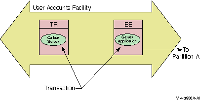
To authenticate any part of a transaction, the callout server must vote on the transaction, but does not write to the database. RTR does not replay a transaction that is only authenticated.
Authentication
RTR callout servers provide facility-based processing for authentication. For example, a callout server can enable verification checks to be carried out on all requests in a given facility.
Callout servers run on backend or router nodes. They receive a copy of every transaction either delivered to or passing through the facility.
Callout servers offer the following advantages:
Because this technique relies on backing out unauthorized transactions, it is most suitable when only a small proportion of transactions are expected to fail the check, so as not to have a performance impact.
Partition
When working with database systems, partitioning the database can be essential to ensuring smooth and untrammeled performance with a minimum of bottlenecks. When you partition your database, you locate different parts of your database on different disk drives to spread both the physical storage of your database onto different physical media and to balance access traffic across different disk controllers and drives.
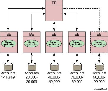
For example, in a banking environment, you could partition your database by account number, as shown in Figure 1-18. A partition is a part or segment of your database.
Figure 1-18 Bank Partitioning Example
Key range
Once you have decided to partition your database, you use key ranges in your application to specify how to route transactions to the appropriate database partition. A key range is the range of data held in each partition. For example, the key range for the first partition in the bank partitioning example goes from 00001 to 19999.
You can assign a partition name in your application program or have it set by the system manager. Note that sometimes the terms key range and partition are used as synonyms in code examples and samples with RTR, but strictly speaking, the key range defines the partition. A partition has both a name, its partition name, and an identifier generated by RTR --- the partition ID. The properties of a partition (callout, standby, shadow, concurrent, key segment range) can be defined by the system manager with a CREATE PARTITION command. For details of the command syntax, refer to the Reliable Transaction Router System Manager's Manual.
A significant advantage of the partitioning shown in the bank example is that you can add more account numbers without making changes to your application; you need only add another server and disk drive for the new account numbers. For example, say you need to add account numbers from 90,000 to 99,999 to the basic configuration of Figure 1-18, Bank Partitioning Example. You can add these accounts and bring them on line easily. The system manager can change the key range with a command, for example, in an overnight operation, or you can plan to do this during scheduled maintenance.
A partition can also have multiple standby servers.
Standby Server Configurations
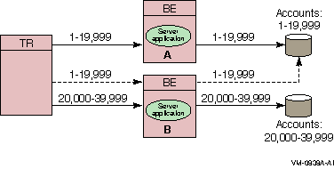
A node can be configured as a primary server for one key range and as a standby server for another key range. This helps to distribute the work of the standby servers. Figure 1-19 illustrates this use of standbys with distributed partitioning.
As shown in Figure 1-19, the Server application on backend A is the primary server for accounts 1 to 19,999 and the Server application on backend B is the standby for these same accounts, shown as a dashed line. The Server application on backend B is the primary for accounts 20,000 to 39,999 and the Server application on backend A can be the standby for these same accounts (not shown in the figure). For clarity, account numbers are shown only for the primary servers and one standby server.
Figure 1-19 Standby with Partitioning
Anonymous clients
RTR supports anonymous clients; that is, clients can be set up in a configuration using wildcarded node names.
Tunnel
RTR can also be used with firewall tunneling software, which supports secure internet communication for an RTR connection, either client-to-router, or router-to-backend.
Depending on operating system, RTR uses TCP/IP or DECnet as underlying transports for the virtual network (RTR facilities) and can be deployed in both local area and wide area networks. PATHWORKS 32 is required for DECnet configurations on Windows NT.
This chapter introduces concepts on basic transaction processing and RTR architecture.
RTR is based on a three-tier physical architecture consisting of frontend (FE) roles, backend (BE) roles and router (TR) roles. The roles are shown in Figure 2-1. (In this and subsequent diagrams, rectangles represent physical nodes, ovals represent application software, and cylinders represent the disks storing the database. The nodes connected to the actual database usually run the database software that controls the database.)
In addition to the physical configuration where RTR is deployed, software plays a critical part, extending the tier concept to more than three tiers. On certain pieces of hardware, client application software runs, and on others, server application software runs. Users can connect to nodes that are running the frontend role with appropriate non-RTR software. For example, a user can have a PC where RTR runs; in this case, the PC has the frontend role. Or a user could use a PC running, say Pathworks, to connect to another node that has the frontend role and run the RTR client application from there. This would be a multitier configuration.
Figure 2-1 The Multitier Model
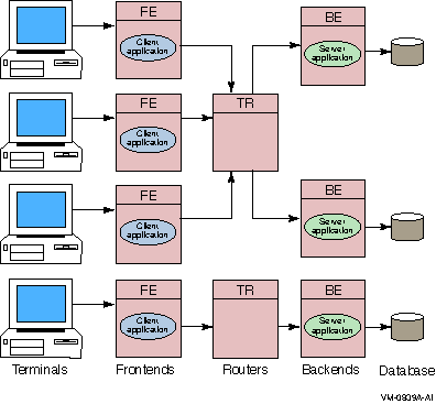
Client application processes run on nodes defined to have the frontend role. This tier allows computing power to be provided locally at the end-user site for transaction acquisition and presentation.
Server application processes (represented by "Server application" in Figure 2-1) run on nodes defined to have the backend role. This tier:
The router tier contains no application software unless running callout servers. This tier reduces the number of logical network links required on frontend and backend nodes and helps ensure good performance even in an unstable network. It also decouples the backend tier from the frontend tier so that configuration changes in the (frequently changing) user environment have little influence on the transaction processing and database (backend) environment.
The three-tier model can be mapped to any system topology. More than one role may be assigned to any particular node. For example, on a system with few frontends, the router and backend tiers can be combined in the same nodes. During application development and test, all three roles can be combined in one node.
The nodes used by an application and their configuration roles are specified using RTR configuration commands. RTR lets application code be completely location and configuration independent.
Many applications can use RTR at the same time without interfering with one another. This is achieved by defining a separate facility for each application. A facility can be thought of as an application network.
For example, when an application calls the C++ API RTRFacilityManager to manage a channel or the C API rtr_open_channel() routine to declare a channel as a client or server, it specifies the name of the facility it will use.
Refer to the Reliable Transaction Router System Manager's Manual for information on how to define facilities.
Sometimes an application has a requirement to send unsolicited messages to multiple recipients.
An example of such an application is a commodity trading system, where the clients submit orders and also need to be informed of the latest price changes.
The RTR broadcast capability meets this requirement.
Recipients subscribe to a class of broadcasts; a sender broadcasts a message in this class, and all interested recipients receive the message. However, broadcast reception is not guaranteed; network or node outages can cause a particular client to fail to receive a broadcast message.
RTR permits clients to broadcast messages to one or more servers, or servers to broadcast to one or more clients. If a server needs to broadcast a message to another server, it must open a second channel as a client.
| Previous | Next | Contents | Index |