HP OpenVMS Systems Documentation |
DECnet-Plus for OpenVMS
|
| Previous | Contents | Index |
An address is a tower set that describes the protocols needed to establish a connection with a node. Tower sets are stored in the namespace. Output is similar to the following display. Each line of a tower corresponds to a network protocol layer.
ncl> show node 0 address |
Node 0
AT 1996-03-14-10:59:41.194-05:00I8.917

Identifiers

    Address                           =
        {
            (
                [ DNA_CMIP-MICE ] ,                         (1)
                [ DNA_SessionControlV3 , number=19 ] ,      (2)
                [ DNA_OSItransportV1 , 'DEC0'H ] ,          (3)
                [ DNA_OSInetwork , 49::00-0C:AA-00-04-00-50-30:21 ](4)
            ) ,
            (
                [ DNA_CMIP-MICE ] ,
                [ DNA_SessionControlV3 , number=19 ] ,
                [ DNA_NSP ] ,        (5)
                [ DNA_OSInetwork , 49::00-0C:AA-00-04-00-50-30:20 ]
            ) ,
            (
                [ DNA_CMIP-MICE ] ,
                [ DNA_SessionControlV3 , number=19 ] ,
                [ DNA_OSItransportV1 , 'DEC0'H ] ,
                [ Internet_IP , 16.20.120.120 ]             (6)
            )
        }
|
The following examples illustrate how the show command displays information about an end node routing circuit on a LAN. You can display information about other entities in the same way.
ncl> show routing circuit csmacd-0 |
Node 0 Routing Circuit CSMACD-0 at 1995-02-26-09:56:26.148-05:00I0.368 Identifiers Name = CSMACD-0 |
ncl> show routing circuit csmacd-0 state |
Node 0 Routing Circuit CSMACD-0 at 1995-02-26-09:28:15.032-05:00I0.264 Status State = On |
ncl> show routing circuit csmacd-0 manual data link sdu size |
Node 0 Routing Circuit CSMACD-0 at 1995-02-26-09:30:24.882-05:00I0.277 Characteristics Manual Data Link SDU Size = 1492 |
ncl> show routing circuit csmacd-0 circuit changes |
Node 0 Routing Circuit CSMACD-0 at 1995-02-26-09:31:29.597-05:00I0.328 Counters Circuit Changes = 1 |
ncl> show routing circuit csmacd-0 all counters |
Node 0 Routing Circuit CSMACD-0 at 1995-02-26-09:43:23.042-05:00I0.235 Counters Data PDUs Received = 0 Data PDUs Fragmented = 0 Data PDUs Transmitted = 5075 Circuit Changes = 1 Initialization Failures = 0 Control PDUs Sent = 12134 Control PDUs Received = 0 Corrupted Hello PDUs Received = 0 Creation Time = 1995-02-25-06:29:17.389-05:00Iinf |
ncl> show routing circuit csmacd-0 all |
Node 0 Routing Circuit CSMACD-0
 at 1995-02-26-09:46:16.622-05:00I0.253

Identifiers
 Name                              = CSMACD-0

Status
 UID                               = 756F4BB0-58F3-CA11-8008-AA000400784D
 State                             = On
 Data Link SDU Size                = 1492
 Data Link Port                    = CSMA-CD Port ETA

Characteristics
 Type                              = CSMA-CD
 Template                          = ""
 Data Link Entity                  = CSMA-CD Station CSMACD-0
 Enable PhaseIV Address            = True
 Manual Data Link SDU Size         = 1492
 Manual Routers                    = {}
 Inactive Area Address             = {}

Counters
 Data PDUs Received                = 0
 Data PDUs Fragmented              = 0
 Data PDUs Transmitted             = 5077
 Circuit Changes                   = 1
 Initialization Failures           = 0
 Control PDUs Sent                 = 12161
 Control PDUs Received             = 0
 Corrupted Hello PDUs Received     = 0
 Creation Time                     = 1995-02-25-06:29:17.389-05:00Iinf
|
Use the following logical names to obtain status about network startup and configuration:
$ show logical net$startup_status |
"NET$STARTUP_STATUS" = "RUNNING-ALL" (LNM$SYSTEM_TABLE) |
The DECnet-Plus software reports significant events that occur during network operation. An event is an occurrence of a normal or abnormal condition detected by an entity. You can control the types of events that DECnet-Plus records for specific or general categories of events by using NCL. These event records help you track the status of network components.
Many events are informational. They record changes to network components on both local and remote systems. Other events report potential or current problems in the physical parameters of the network.
An event report identifies the originating entity and the time when the event occurred. For those entities that report events, the DECnet-Plus Network Control Language Reference lists the events, the reason the event occurred, and any arguments reported to the event dispatcher.
You can set up event dispatching on a particular system, between two
systems, or across multiple, distributed systems. Events that occur on
systems running DECnet Phase IV or Phase V software can be reported by
the DECnet-Plus event dispatching function.
12.1 Event Dispatching Concepts
When an entity notices that a condition has occurred, it generates an event message. The entity posts the event message and the local event dispatcher picks it up. The event dispatcher examines the user-defined event filters for each outbound stream created on the system. The event filter lets you selectively disable or enable the reporting of events based on the entity class and event type, or the specific entity instance and event type. If the event message passes the event filter, the message is given to the corresponding outbound stream.
An outbound stream maintains a queue of event messages waiting to be sent to their destination. After passing through the filter defined for the outbound stream, the event message is sent to an event logging component, called an event sink. An event sink can be on the same system, or a different system, as the outbound streams. When the event source and the event sink are on the same system, the outbound stream forwards the event report directly to the event sink. When the event sink is on a different system, the outbound stream encodes the event report in the form of DIGITAL Network Architecture Common Management Information Protocol (DNA CMIP) calls, and forwards the DNA CMIP message to the corresponding event sink on the designated remote system.
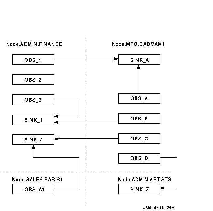
For each outbound stream, there is a single associated event sink. However, a single event sink might process incoming event messages from more than one outbound stream. Systems can have a combination of outbound streams and event sinks (see Figure 12-1). You determine the actual event dispatching configuration established in your network.
Figure 12-1 Relationship of Outbound Streams and Event Sinks

The event sink accepts the incoming connection and creates an inbound stream entity to represent the connection. A sink can have multiple inbound streams, one for every outbound steam associated with the sink. The inbound stream remains for the life of the association between the outbound stream and the event sink. This connection can receive many event messages. Inbound streams are deleted when the connection between the outbound stream and the event sink is deleted.
An event sink maintains a queue of events waiting to be processed by another event logging component called the event sink client. Event sink clients are applications that process the event messages for you. The event dispatcher provides default event sink clients.
You can record events that occur on systems running Phase IV software by defining a relay on a DECnet Phase V system.
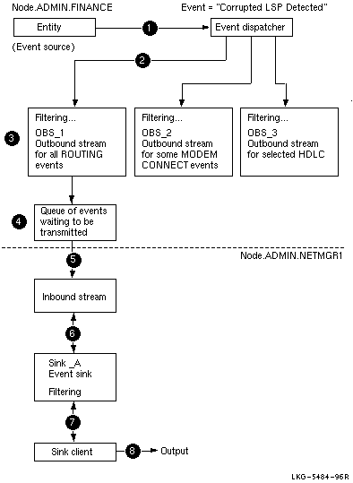
Figure 12-2 follows the path of a sample event report from a source, the routing entity on the .admin.finance system, to a sink on the .admin.netmgr1 system. A numbered list follows Figure 12-2 and explains the event dispatching sequence.
Figure 12-2 Sample Event Dispatching Sequence

You can define event filters with outbound streams, event sinks, or both outbound streams and event sinks. This section explains how the filtering process works.
Event filters let you:
You can establish filters:
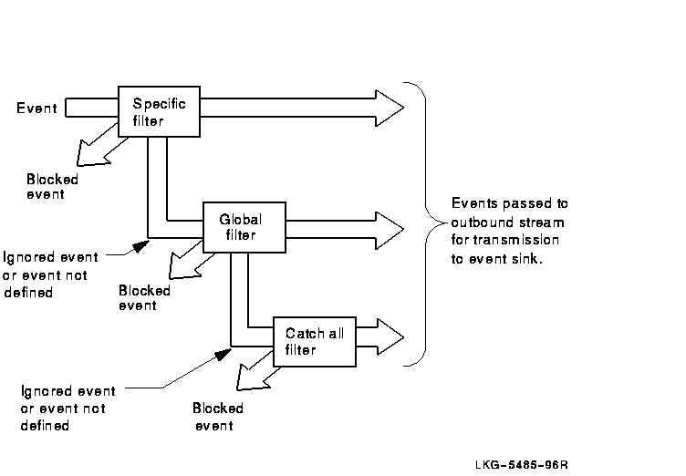
Event filters have three settings, which DECnet-Plus searches through in this order: first, specific filter setting; then, global filter setting; and finally, catch-all filter setting. The first filter that applies to an event is used to discard the event or enter it into the dispatching stream.
The options (from the perspective of the outbound stream entity) are to:
To see which filters are currently in place, check the following files:
SYS$STARTUP:NET$EVENT_STARTUP.NCL
SYS$MANAGER:NET$EVENT_LOCAL.NCL
You may not need to change the event filters at all, unless you want to handle them differently than the defaults shown in that file.
If an entity is not included in the specific or global filter display, this means that the event action for all events of that entity (instance or class) is ignore.
Figure 12-3 shows the sequence of filtering through the hierarchy of event filters.
Figure 12-3 Sequence of Event Filtering

You cannot use wildcard characters with the entity class name or instance name in the definition of a filter's specific setting. |
See Section 12.3.14 for examples of using filtering with outbound
stream entities, and Section 12.3.5 for filtering examples for
event sink entities.
12.3 Setting Up and Using Event Dispatching
The following sections describe how to set up and use the event dispatcher.
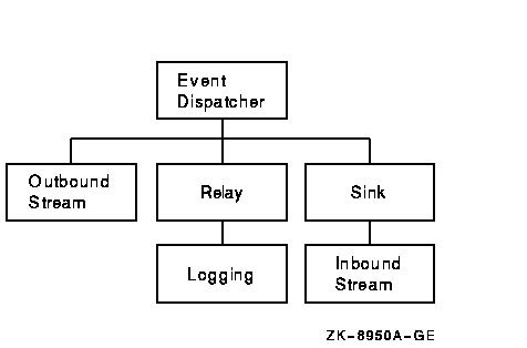
Section F.1 provides a simple example that takes the defaults of setting up the event dispatcher. Figure 12-4 shows the event dispatcher entity and subentities.
Figure 12-4 event dispatcher Entity

By default, the event dispatcher entity is created and enabled on the local system in its script file. Thus, you may not need to start it yourself.
Use the NET$CONFIGURE.COM procedure to configure the event dispatcher. The event dispatcher usually starts as part of the NET$STARTUP procedure. If the NET$EVENT_STARTUP.NCL script file exists, the software creates the event dispatcher, invokes the event dispatcher script file (which creates and enables outbound streams, sinks, and relay), and enables the event dispatcher.
DIGITAL recommends that you do not disable the event dispatcher at startup. If you do not wish to receive events, you can add the following command to SYS$MANAGER:NET$EVENT_LOCAL.NCL:
set event dispatcher outbound stream * catch all filter block |
This NCL script is described in Section 6.2.3.
On an OpenVMS system, before the event dispatcher is enabled, event messages are queued. The messages wait for the event dispatcher to process them. After the event dispatcher is enabled, it can begin processing events. |
You can use the following commands to check if the event dispatcher and its associated outbound streams and sinks states are enabled:
ncl> show event dispatcher state ncl> show event dispatcher outbound stream * state ncl> show event dispatcher sink * state |
If you attempt to use the event dispatcher, an outbound stream, or a sink that is not available, you will receive an error indicating that the command failed for the following reason:
no such object instance
You can start the event dispatcher after running NET$STARTUP with the following command:
$ @sys$system:startup network evd |
Each event generated on a system is filtered through each outbound stream. The stream delivers the event to a particular event sink that exists on the local system or a remote system. If you set up more than one outbound stream, each outbound stream is affiliated with one sink. An event sink can accept event reports from one or more outbound streams, which can reside on the same or different system as the event sink.
Each outbound stream is represented by an event dispatcher outbound stream entity. Each event sink is represented by an event dispatcher sink entity.
When you establish outbound streams and event sinks, you:
Subsequent sections describe the steps you need to take to set up outbound streams and event sinks.
| Previous | Next | Contents | Index |